Mold grinding and cleaning equipment

A technology for cleaning equipment and molds, which is applied in the direction of grinding/polishing equipment, metal processing equipment, grinding machines, etc., and can solve problems such as inability to fix molds, lack of cleaning functions, and poor grinding quality

Inactive Publication Date: 2021-09-14
谢森涛
View PDF0 Cites 2 Cited by
  • Summary
  • Abstract
  • Description
  • Claims
  • Application Information

AI Technical Summary

Problems solved by technology

[0004] The purpose of the present invention is to solve the problem that the mold grinding equipment in the prior art cannot easily and conveniently fix the mold when grinding the mold, resulting in poor grinding quality, and the general grinding equipment does not have the cleaning function, resulting in dust Residue inside the mold, which affects its later use, and a mold grinding and cleaning equipment is proposed

Method used


Image

  • Mold grinding and cleaning equipment
  • Mold grinding and cleaning equipment
  • Mold grinding and cleaning equipment

Examples


Embodiment 1

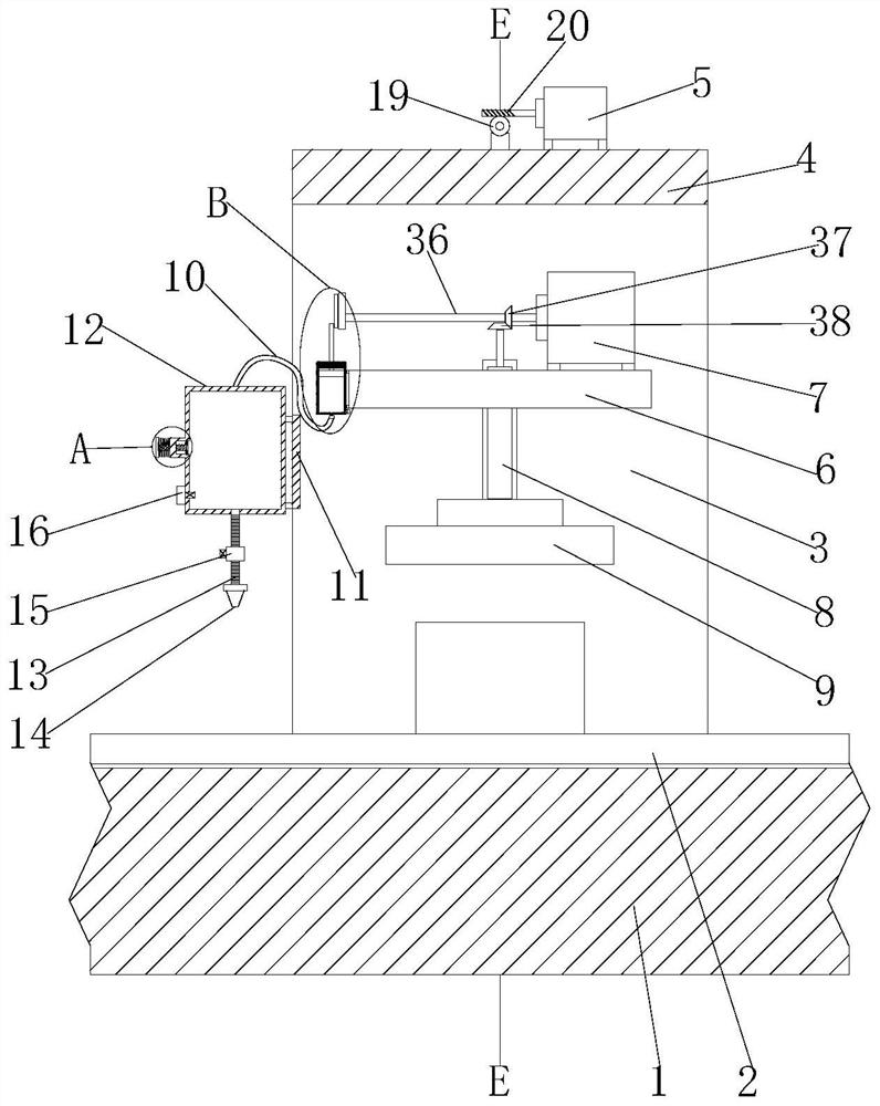
[0030] refer to Figure 1-6 , a mold grinding and cleaning equipment, including a base 1, the top of the base 1 is provided with a transmission plate 2, and the top of the base 1 is fixedly connected with two support plates 3 by welding, and the top ends of the two support plates 3 are fixedly connected by welding. The same top plate 4, the top of the top plate 4 is fixed with a first motor 5 by bolts, the side of the two supporting plates 3 close to each other is rotated and installed with the same lifting plate 6, and the top of the lifting plate 6 is fixed with a second motor 5 by bolts. The motor 7, the lifting plate 6 are provided with a rotating hole, and the rotating hole is equipped with a grinding shaft 8, and the bottom end of the grinding shaft 8 is fixedly connected with a grinding wheel 9 by welding, and the grinding shaft 8 is matched with the second motor 7, and the base 1 Two clamping mechanisms are arranged on the top of the top, and the two clamping mechanism...

Embodiment 2

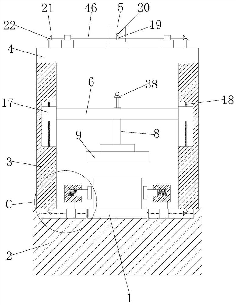
[0042] The difference from Embodiment 1 is that the output shaft of the first motor 5 is connected with the seventh bevel gear, the outer fixed sleeve of the rotating rod 46 is provided with the eighth bevel gear, and the eighth bevel gear meshes with the seventh bevel gear .

[0043] In the present invention, when in use, the mold that needs to be polished is placed on the transmission plate 2, and the transmission plate 2 drives the mold to be displaced to directly below the grinding wheel 9 and then stops. At this time, the output shaft of the first motor 5 drives the seventh bevel gear Rotate, the seventh bevel gear drives the eighth bevel gear to rotate, the eighth bevel gear drives the rotating rod 46 to rotate, the rotating rod 46 drives the first bevel gear 21 to rotate, the first bevel gear 21 drives the second bevel gear 22 to rotate, the second bevel gear The gear 22 drives the first screw rod 18 to rotate, the first screw rod 18 drives the first slider 17 to move d...


PUM


Abstract

The invention belongs to the field of mold machining, and particularly relates to mold grinding and cleaning equipment which comprises a base. A transmission plate is arranged at the top of the base, two supporting plates are fixedly connected to the top of the base, the top ends of the two supporting plates are fixedly connected with the same top plate, a first motor is fixedly mounted at the top of the top plate, the same lifting plate is rotatably mounted on the sides, close to each other, of the two supporting plates, a second motor is fixedly mounted at the top of the lifting plate, a rotating hole is formed in the lifting plate, a grinding shaft is rotatably mounted in the rotating hole, a grinding wheel is fixedly connected to the bottom end of the grinding shaft, the grinding shaft cooperates with the second motor, two clamping mechanisms are arranged at the top of the base, and the two clamping mechanisms cooperate with the first motor. During use, a mold can be simply and conveniently fixed so that the mold cannot shake during grinding, the grinding quality is improved, the air pressure in an air storage tank can be indirectly increased during rotation of the grinding wheel, and therefore the purpose of flushing the mold through the air pressure is achieved.

Description

technical field [0001] The invention relates to the technical field of mold processing, in particular to a mold grinding and cleaning equipment. Background technique [0002] Mold, various molds and tools used in industrial production for injection molding, blow molding, extrusion, die-casting or forging forming, smelting, stamping and other methods to obtain the required products. In short, a mold is a tool used to make shaped objects. This tool is composed of various parts, and different molds are composed of different parts. It mainly realizes the processing of the shape of the object through the change of the physical state of the formed material. After the general mold production is completed, the mold needs to be further processed by grinding equipment, and some unevenness on the surface of the mold should be polished, so as to improve the quality of the products produced by the later mold. [0003] However, the existing mold grinding equipment often cannot fix the mo...

Claims


Application Information

Patent Timeline
Patent Type & Authority Applications(China)
IPC IPC(8): B24B19/20B24B41/06B24B55/06B08B5/02
CPCB24B19/20B24B41/06B24B55/06B08B5/02
Inventor 谢森涛
Owner 谢森涛
Why Eureka
Try Eureka