Auxiliary instrument for repairing skin flap into skin graft
A technology of skin flaps and skin grafts, applied in the field of burn plastic surgery, can solve problems such as adverse effects of skin tissue, hand slippage, and high requirements for doctors
- Summary
- Abstract
- Description
- Claims
- Application Information
AI Technical Summary
Problems solved by technology
Method used
Image
Examples
Embodiment 1
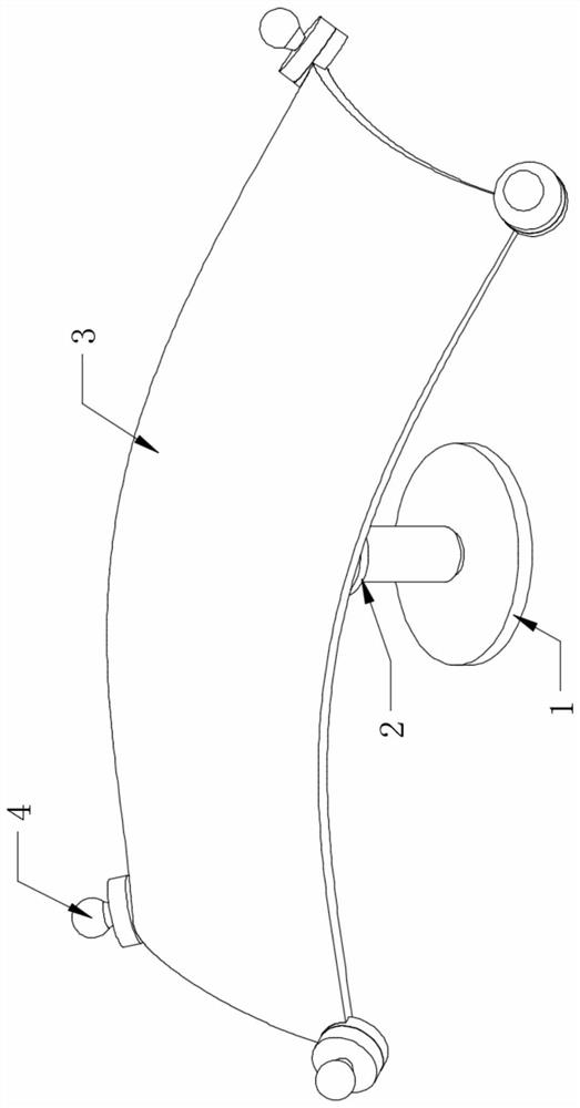
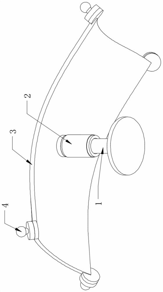
[0041] Such as Figure 1-Figure 12 As shown, an auxiliary instrument for repairing skin flaps according to an embodiment of the present invention includes a support base 1, a movable support column 2, a flap support plate 3 and a fixed buckle 4, and the movable support column 2 is sleeved on the support base 1 The surface of the movable support column 2 is threadedly connected with the support base 1, the flap support plate 3 is welded on the top of the movable support column 2, the number of fixed buckles 4 is four, and the four fixed buckles 4 are respectively welded on the flap The four corners of support plate 3.
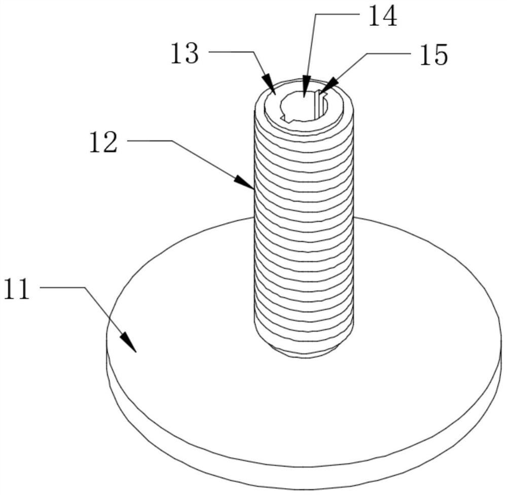
[0042]Wherein, the support base 1 includes a support disc 11, a threaded sleeve 12, and a limit support column 13. The limit support column 13 is inserted on the top of the support disc 11, and the limit support column 13 is located at the center of the support disc 11 top At the position, the threaded sleeve 12 is sleeved on the surface of the limit support co...
Embodiment 2
[0057] More specifically, such as Figure 5 As shown, the difference between this embodiment and the above embodiment is that the surface of the rotating sleeve 24 is covered with a silicone anti-slip sleeve 25, the inner wall of the silicone anti-slip sleeve 25 is bonded to the rotating sleeve 24, and the surface of the silicone anti-slip sleeve 25 is set There are anti-slip lines, and by adopting the above-mentioned technical solution, the friction force between the hand and the rotating sleeve 24 can be improved when the rotating sleeve 24 is turned, and the situation of slipping when rotating the rotating sleeve 24 is avoided.
Embodiment 3
[0059] More specifically, such as Figure 4 with 8 The difference between this embodiment and the above-mentioned embodiment is that the two limiting posts 27 are respectively located in the inner cavities of the two limiting grooves 15, and the limiting posts 27 are slidably connected with the limiting grooves 15. By using the above technical solution, It is possible to limit the post 26, avoiding that when the rotary connection ring 23 rotates, the rotary connection ring 23 drives the rotation limiter 211, the connection ring 210, the fixed collar 22 and the fixed post 21 to rotate through friction, thereby causing the post to be inserted. 26 follow the rotating situation, which improves the stability of the replicating apparatus.
PUM
 Abstract
Description
Claims
Application Information
 - Generate Ideas
- Intellectual Property
- Life Sciences
- Materials
- Tech Scout
- Unparalleled Data Quality
- Higher Quality Content
- 60% Fewer Hallucinations
Browse by: Latest US Patents, China's latest patents, Technical Efficacy Thesaurus, Application Domain, Technology Topic, Popular Technical Reports.
© 2025 PatSnap. All rights reserved.Legal|Privacy policy|Modern Slavery Act Transparency Statement|Sitemap|About US| Contact US: help@patsnap.com


