
Automatic instrument identification method and system

A technology for automatic identification and instrumentation, which is applied in the field of image processing and can solve problems such as low efficiency, low reading efficiency, and errors.

Pending Publication Date: 2021-09-10
刘胜娃 +10
View PDF0 Cites 1 Cited by
  • Summary
  • Abstract
  • Description
  • Claims
  • Application Information

AI Technical Summary

Problems solved by technology

[0003] At present, the instruments used by the drilling team to measure parameters such as drilling fluid friction, mud pump pressure, standpipe pressure, and drilling pressure at the well site are all analog pointer instruments, which require operators to read and record the current values ​​regularly. On the one hand, it is easy to Make mistakes and generate reading errors; on the other hand, it needs to consume a lot of manpower and material resources, the reading efficiency is low, and the misjudgment rate is high
[0004] At present, the automatic identification of instruments needs to pre-select and establish an instrument model library, and match the collected images with the instrument model to identify the type of instrument and then read. However, there are many types of instruments and fewer characteristic values. This method is in the template Matching errors are prone to occur during the automatic matching process, resulting in errors in readings, usually requiring manual correction of the template, which is inefficient

Method used


Image

  • Automatic instrument identification method and system
  • Automatic instrument identification method and system
  • Automatic instrument identification method and system

Examples


Embodiment Construction

[0034] In order to make the purpose, technical solutions and advantages of the embodiments of the present invention clearer, the technical solutions in the embodiments of the present invention will be clearly and completely described below in conjunction with the drawings in the embodiments of the present invention. Obviously, the described embodiments It is a part of embodiments of the present invention, but not all embodiments. Based on the embodiments of the present invention, all other embodiments obtained by persons of ordinary skill in the art without making creative efforts belong to the protection scope of the present invention.

[0035] Below in conjunction with accompanying drawing, the present invention is described in further detail:

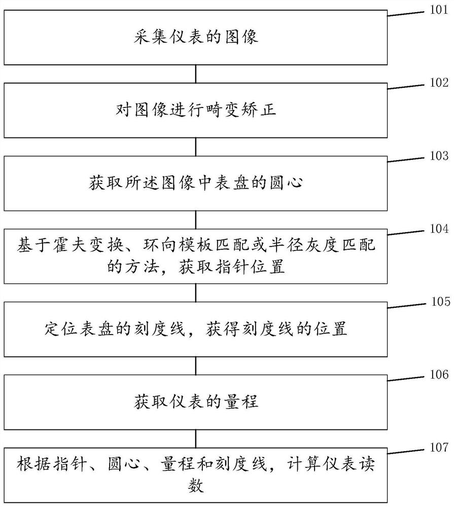
[0036] A method for automatic instrument identification, such as figure 1 As shown, the method includes:

[0037] Step 101: Collect the image of the meter. You can install a camera in front of the instrument to collect the image o...


PUM


Abstract

The invention discloses an automatic instrument identification method and system, and belongs to the technical field of image processing, and the method comprises the steps of collecting an image of an instrument; carrying out distortion correction on the image; acquiring the circle center of a dial plate in the image; obtaining a pointer position based on a Hough transform, circumferential template matching or radius gray scale matching method; positioning the scale marks of the dial plate to obtain the positions of the scale marks; obtaining the measuring range of the instrument; and calculating instrument readings according to the pointer, the circle center, the measuring range and the scale marks. Through the image processing technology of machine vision, the circle center, the pointer, the measuring range and the scale marks of the instrument are recognized, and the count of the instrument is calculated to replace manual counting, so that the recognition efficiency and accuracy are improved, and manpower and material resources are saved; and a reading error caused by an instrument template matching error is avoided.

Description

technical field [0001] The invention relates to the technical field of image processing, in particular to a method and system for automatic instrument identification. Background technique [0002] Mechanical instruments, such as pointer instruments, are widely used in various processing fields such as petroleum and coal. They have the advantages of strong anti-interference, dust-proof, waterproof, and long life, especially for fire-proof and explosion-proof occasions and harsh environments, such as electric power , petroleum, chemical industry, etc., the pointer instrument is still the first choice. [0003] At present, the instruments used by the drilling team to measure parameters such as drilling fluid friction, mud pump pressure, standpipe pressure, and drilling pressure at the well site are all analog pointer instruments, which require operators to read and record the current values ​​regularly. On the one hand, it is easy to Make mistakes and generate reading errors; ...

Claims


Application Information

Patent Timeline
IPC IPC(8): G06K9/20G06K9/62G06T7/11G06T7/62
CPCG06T7/62G06T7/11G06F18/22
Inventor 刘胜娃曹湘华陈琪王建胜隗崇华林海军王茗骏乔维胡刚李庆华张琦
Owner 刘胜娃
Learn More