Frame type embankment pond structure

A frame-type embankment technology, applied to underwater structures, infrastructure engineering, embankments, etc., can solve the problems affecting the aesthetics of embankments, the distance between the sightseeing corridor on the embankment and the green belt on the bank, and the difficulty of construction in deep water areas, etc.

Active Publication Date: 2021-09-10
温州市水利电力勘测设计院有限公司
View PDF6 Cites 1 Cited by
  • Summary
  • Abstract
  • Description
  • Claims
  • Application Information

AI Technical Summary

Problems solved by technology

[0006] At the same time, as the embankment line of the embankment in the deep water section moves outward, there are not only difficulties in the construction of the deep water area (such as the foundation construction of the bearing platform), but also the distance between the sightseeing corridor on the embankment crest and the green belt on the bank is too large, which affects the overall greening of the embankment beauty of design

Method used


Image

  • Frame type embankment pond structure
  • Frame type embankment pond structure
  • Frame type embankment pond structure

Examples


Embodiment Construction

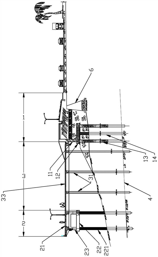
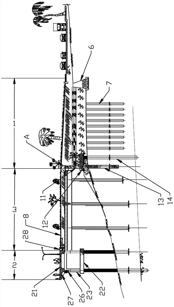
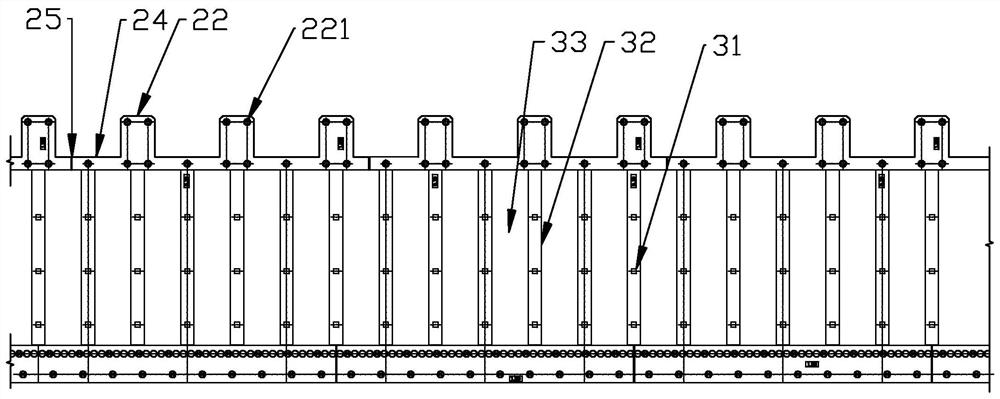
[0033] Such as Figure 1-5 As shown, a frame-type embankment structure includes a solid filling section 1 arranged at the existing shoreline, a cap section 2 set in a deep water area, and a frame section 3 connecting the two sections. The solid filling section 1 includes A wave wall 11 and a fixed base 12, the fixed base 12 is sequentially provided with a dense row of cast-in-place pile walls 13 and a number of cast-in-place piles 14 entering the pebble bearing layer 4 along the direction from the water to the shore; the cap section 2 includes embankment The top platform 21, some caps 22 and some pillars 23, the pillars 23 are arranged between the caps 22 and the embankment top platform 21 to support the embankment top platform 21, and the caps 22 are provided with a number of pebble bearing layers 4 The PHC pile 221; the frame section 3 includes a number of prefabricated square piles 31 entering the pebble bearing layer 4, a concrete cast-in-place roof beam 32 arranged on the...


PUM


Abstract

The invention discloses a frame type embankment pond structure. The frame type embankment pond structure comprises a solid filling section arranged at an existing shoreline, a bearing platform section arranged in a deep water area and a frame section connecting the solid filling section, wherein the solid filling section comprises a wave wall and a fixed base, the fixed base is sequentially provided with a densely-arranged cast-in-place pile wall entering a pebble bearing layer and a plurality of cast-in-place piles in the direction from water to the shore, the bearing platform section comprises an embankment top platform, a plurality of bearing platforms and a plurality of supporting columns, the supporting columns are arranged between the bearing platforms and the embankment top platform and support the embankment top platform, a plurality of PHC piles entering a pebble bearing layer are arranged on the bearing platforms, the frame section comprises a plurality of prefabricated square piles entering the pebble bearing layer, a concrete cast-in-place top girder arranged at the tops of the prefabricated square piles and a concrete cast-in-place top plate laid on the concrete cast-in-place top girder, the concrete cast-in-place top plate is connected with the embankment top platform and the wave wall, pile tips of the prefabricated square piles are H-shaped steel sheet pile shoes, the wave wall and the concrete cast-in-place top girder are arranged in a split mode, connecting bosses are arranged at the adjacent positions of the wave wall and the concrete cast-in-place top girder, and a concrete cast-in-place top plate is laid between the connecting bosses.

Description

technical field [0001] The invention relates to the technical field of flood control embankments, in particular to a frame type embankment structure. Background technique [0002] Most plain rivers in my country have very frequent and severe flood disasters. Such rivers are usually composed of main channels and flats, and their cross-sections are complex and complex. After the water floods the beach during the flood, the river channel relies on the main channel and the beach to discharge the flood together. Due to various natural reasons and the adverse effects of human factors, many river courses are seriously silted up and have poor flood discharge capacity, which seriously threatens the safety of people's lives and properties. [0003] On the other hand, with the rapid development of the national economy, in order to improve flood control standards, many river embankments have been rerouted, and the beach land has been widely used. Many river beaches have been used as cu...

Claims


Application Information

Patent Timeline
IPC IPC(8): E02B3/06E02B3/10E02D27/12E02D27/14E02D29/02E02D5/50E02D5/58E02D5/72E02B8/06
CPCE02B3/06E02B3/068E02B3/066E02B3/10E02D27/12E02D27/14E02D29/02E02D5/50E02D5/58E02D5/72E02B8/06Y02A10/30Y02A10/11
Inventor 孙永义黄一彬余玉龙陈开谱吴道合张迈陈君蔡富陈德仕田小平安然陈承洁郭威王奔徐炳林张敬华陈青青娄一青林加定唐斌
Owner 温州市水利电力勘测设计院有限公司
Why Eureka
Try Eureka