Quick Alignment Tool and Method for Large Aeronautical Structural Parts
A kind of aviation structural parts, fast technology, applied in the direction of manufacturing tools, metal processing equipment, metal processing machine parts, etc., can solve the problems of the impact force is not easy to control, the straightness of parts is difficult, the labor intensity of workers is high, etc., to reduce The effect of repeated correction times, strong versatility, and easy control of correction strength
- Summary
- Abstract
- Description
- Claims
- Application Information
AI Technical Summary
Problems solved by technology
Method used
Image
Examples
Embodiment 1
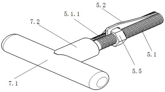
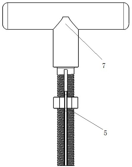
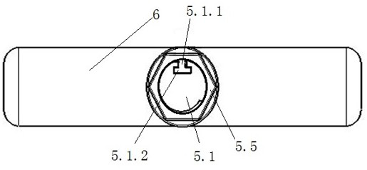
[0044] This embodiment discloses a quick alignment tool for large aeronautical structural parts. As a basic embodiment of the present invention, it includes a correction mechanism 5 and a force-applying handle 7; the correction mechanism 5 includes a support stud 5.1, a correction plate 5.2 and an adjustment nut 5.5; one end of the supporting stud 5.1 is provided with a connecting terminal 6, and the supporting stud 5.1 is detachably fixedly connected with the force applying handle 7 through the connecting terminal 6; the side of the supporting stud 5.1 is along the length direction of the supporting stud 5.1 A linear chute 5.1.1 is provided, and the linear chute runs through the other end of the supporting stud 5.1; the adjusting nut 5.5 is spirally connected with the supporting stud 5.1; one side of the correction plate 5.2 is provided with a linear matching edge 5.2.1 as a whole, and the correction plate Set the arc correction side 5.2.2 on the other side of 5.2; the distanc...
Embodiment 2
[0049] This embodiment discloses a quick alignment tool for large aeronautical structural parts. As a preferred embodiment of the present invention, that is, in Embodiment 1, the connecting end 6 is cylindrically arranged coaxially with the supporting stud 5.1; the connecting end The bottom of the head 6 is fixedly connected with the supporting stud 5.1, and the top of the connecting head 6 is provided with a multi-ribbed groove 6.1 for connecting the force application handle 7; Part 7.2; one end of the connecting part 7.2 is vertically fixedly connected with the middle of the handle part 7.1, and the other end of the connecting part 7.2 is coaxially provided with a cylindrical groove 7.2.1 for clearance matching with the outer wall of the connecting end 6; the cylindrical groove 7.2 The inside of .1 is provided with a multi-ribbon protrusion structure 7.2.2 for cooperating with the multi-ribbon groove 6.1.
[0050] In actual production, the multi-edge groove 6.1 can be set as...
Embodiment 3
[0052] This embodiment discloses a quick alignment tool for large aeronautical structural parts. As a preferred embodiment of the present invention, that is, in Embodiment 1, the connecting end 6 is cylindrically arranged coaxially with the supporting stud 5.1; the connecting end The bottom of the head 6 is fixedly connected with the supporting stud 5.1, and the top of the connecting head 6 is provided with a multi-ribbed groove 6.1 for connecting the force application handle 7; Part 7.2; one end of the connecting part 7.2 is vertically fixedly connected with the middle of the handle part 7.1, and the other end of the connecting part 7.2 is coaxially provided with a cylindrical groove 7.2.1 for clearance matching with the outer wall of the connecting end 6; the cylindrical groove 7.2 The inside of .1 is provided with a multi-ribbon protrusion structure 7.2.2 for cooperating with the multi-ribbon groove 6.1.
[0053] In actual production, the multi-angular groove 6.1 can be set...
PUM
 Abstract
Description
Claims
Application Information
 - R&D
- Intellectual Property
- Life Sciences
- Materials
- Tech Scout
- Unparalleled Data Quality
- Higher Quality Content
- 60% Fewer Hallucinations
Browse by: Latest US Patents, China's latest patents, Technical Efficacy Thesaurus, Application Domain, Technology Topic, Popular Technical Reports.
© 2025 PatSnap. All rights reserved.Legal|Privacy policy|Modern Slavery Act Transparency Statement|Sitemap|About US| Contact US: help@patsnap.com


