
Little bear iron sheet manufacturing equipment

A technology of iron sheet and equipment, which is applied in the field of bear iron sheet production equipment, can solve the problems of high labor intensity, low labor intensity, and low work efficiency.

Active Publication Date: 2021-09-10
星铁航(江苏)教育科技有限公司
View PDF5 Cites 0 Cited by
  • Summary
  • Abstract
  • Description
  • Claims
  • Application Information

AI Technical Summary

Problems solved by technology

[0004] In order to overcome the shortcomings of high manual labor intensity and low work efficiency, the technical problem is to provide a small bear iron sheet production equipment with low manual labor intensity and high work efficiency

Method used


Image

  • Little bear iron sheet manufacturing equipment
  • Little bear iron sheet manufacturing equipment
  • Little bear iron sheet manufacturing equipment

Examples


Embodiment 1

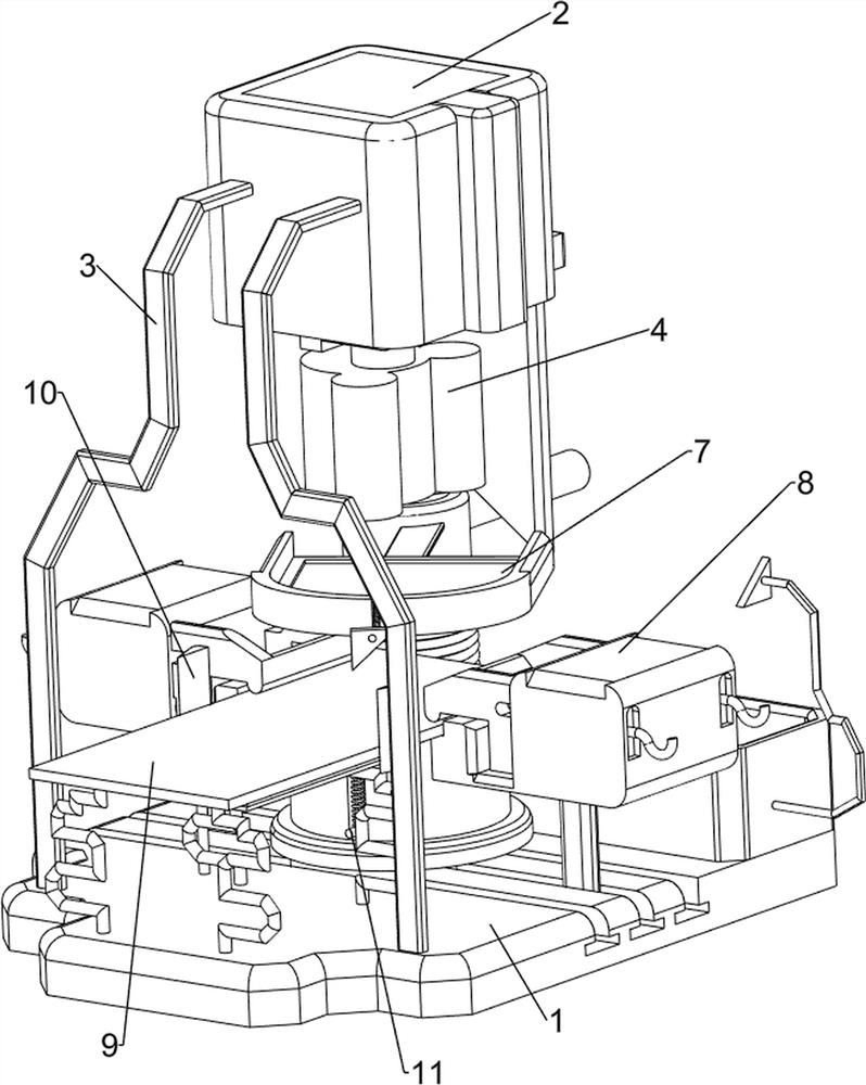
[0059] A bear tin making equipment, such as figure 1 and figure 2 As shown, it includes a base plate 1, a cylinder 2, a first support frame 3, a pressing column 4, a clamping block 5, a forming column 6, a discharge mechanism 7 and a clamping mechanism 8, and the left and right sides of the upper part of the base plate 1 are connected with the second A support frame 3, a cylinder 2 is connected between the rear sides of the first support frame 3, the end of the telescopic rod of the cylinder 2 is connected with a lower pressure column 4, the bottom plate 1 is slidably connected with a block 5, and the upper side of the block 5 is connected with a The forming column 6 is connected with a discharge mechanism 7 on the telescopic rod of the cylinder 2, and the left and right sides of the bottom plate 1 are all slidably connected with a clamping mechanism 8.

[0060] When the device needs to be used, the user can pull the clamping mechanism 8 to the outside, then put the iron she...

Embodiment 2

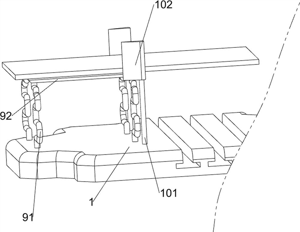
[0062] On the basis of Example 1, such as image 3 As shown, the discharge mechanism 7 includes a first wedge block 71, a support column 72, a first spring 73, a fixed rod 74, a discharge tray 75, a second wedge block 76, a charging box 77, a second support frame 78 and The third wedge-shaped block 79, the first wedge-shaped block 71 is connected on the expansion rod of the cylinder 2, the support column 72 is connected with the rotary type in the base plate 1, and the first spring 73 is connected between the support column 72 outside and the base plate 1, and the support column 72 The rear side is connected with a fixed rod 74, the right side of the support column 72 is connected with a discharge tray 75, and the rotation type in the discharge tray 75 is connected with a second wedge-shaped block 76, and the rear side of the bottom plate 1 is connected with a charging box 77, and the charging box The right side of 77 is connected with a second support frame 78, and the left s...


PUM


Abstract

The invention relates to iron sheet manufacturing equipment, and particularly relates to little bear iron sheet manufacturing equipment. The invention aims to provide the little bear iron sheet manufacturing equipment which is low in manual labor intensity and high in working efficiency. According to the technical scheme, the little bear iron sheet manufacturing equipment comprises a bottom plate, first supporting frames, an air cylinder, a lower pressing column, a clamping block, a forming column, a discharging mechanism and clamping mechanisms, wherein the two sides of the top of the bottom plate are connected with the first supporting frames; the air cylinder is connected between one sides of the first supporting frames; the tail end of a telescopic rod of the air cylinder is connected with the lower pressing column; the clamping block is connected into the bottom plate in a sliding mode; one side of the clamping block is connected with the forming column; the discharging mechanism is connected to the telescopic rod of the air cylinder; and the clamping mechanisms are connected to the two sides of the bottom plate in a sliding mode. According to the little bear iron sheet manufacturing equipment, through cooperation of a first wedge-shaped block, a discharging disc, a second wedge-shaped block and a third wedge-shaped block, the purposes of automatically overturning formed iron sheets and collecting the formed iron sheets are achieved.

Description

technical field [0001] The invention relates to equipment for making iron sheets, in particular to equipment for making iron sheets for bears. Background technique [0002] When cutting the iron sheet, the hand is easy to leave the handle body, which is easy to cause the hand to be injured after touching the cut iron sheet, or the movement direction of the cutter head body changes due to the separation of the human hand, so that the iron sheet is scrapped due to inaccurate cutting. Traditional iron sheet scissors When cutting the iron sheet, the cut iron sheet part will move in any direction, which is easy to hinder the movement of the iron sheet scissors, and also cause incidents such as hand injury. The two handles of the traditional iron sheet scissors are separated. When opening the handle body, due to excessive force, the distance between the two hands is very large, and it will take time and effort when closing it. [0003] Aiming at the iron sheet production process,...

Claims


Application Information

Patent Timeline
IPC IPC(8): B23D79/00B23Q3/06B23Q7/00B23Q11/00
CPCB23D79/00B23Q3/06B23Q7/00B23Q11/0042Y02P70/10
Inventor 潘秋兰
Owner 星铁航(江苏)教育科技有限公司
Learn More