
Mining electro-hydraulic control filter element cleaning device and cleaning method thereof

A cleaning device, electro-hydraulic control technology, applied in separation methods, chemical instruments and methods, fixed filter element filters, etc., can solve problems such as large resistance loss, reduced filter performance, and increased cost.

Pending Publication Date: 2021-09-10
西安重装澄合煤矿机械有限公司
View PDF4 Cites 0 Cited by
  • Summary
  • Abstract
  • Description
  • Claims
  • Application Information

AI Technical Summary

Problems solved by technology

Since the emulsion is prepared by emulsified oil and water at a ratio of 5:95, it is oily in itself, and the impurities in the emulsion are easily attached to the filter screen. After about a month of use, the filter performance of the filter screen will decline. Lots of drag losses
At this time, it is necessary to replace or clean the filter screen. The existing technology does not have an easy-to-clean device for use with it. Replacement will greatly increase the cost and affect the economic benefits of coal mining enterprises.

Method used


Image

  • Mining electro-hydraulic control filter element cleaning device and cleaning method thereof
  • Mining electro-hydraulic control filter element cleaning device and cleaning method thereof
  • Mining electro-hydraulic control filter element cleaning device and cleaning method thereof

Examples


Embodiment Construction

[0024] The present invention will be clearly and completely described below in conjunction with the accompanying drawings, so that those skilled in the art can fully implement the present invention without creative work.

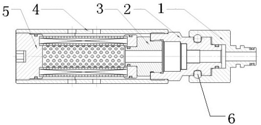
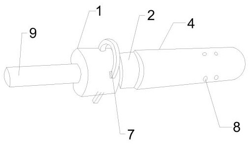
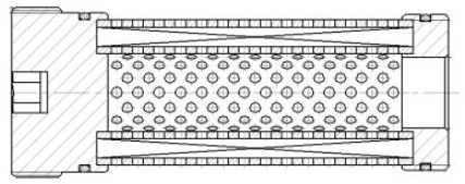
[0025] The specific embodiment of the present invention is: as Figure 1-3 As shown, a mining electro-hydraulic control filter element cleaning device includes an adapter 1, a connecting assembly, a housing 4, and a filter element 5. The body 4 is fixedly connected through a connection assembly, and the other end of the adapter 1 is connected to a mine filter element flow test bench 9, and the connection assembly includes a connection head 2, a connection sleeve 3, and a fixing piece 7. One end is provided with threads, one end is threadedly connected with the filter element 5, and the other end is threadedly connected with the connector 2, and one end of the connector 2 is concaved inward to form a card slot, and an internal thread is provided in the card s...


PUM


Abstract

The invention provides a mining electro-hydraulic control filter element cleaning device and a method thereof. The device comprises an adapter, a connecting assembly, a shell and a filter element, the filter element is fixed in the shell in a matched mode, one end of the adapter is fixedly connected with the shell through the connecting assembly, and the other end of the adapter is connected with a mining filter element flow testing table; the connecting assembly comprises a connector, a connecting sleeve and a fixing piece, threads are arranged on the side faces of the two ends of the connecting sleeve, one end of the connecting sleeve is in threaded connection with the filter element, the other end of the connecting sleeve is in threaded connection with the connector, one end of the connector is concaved inwards to form a clamping groove, internal threads are arranged in the clamping groove to be connected with the connecting sleeve, and the outer side face of the connector is in threaded connection with the shell. Two mounting holes are correspondingly formed in the other end of the connector and the adapter, the fixing piece penetrates through the mounting holes to fixedly connect the connector and the adapter, and a plurality of drainage holes are formed in the outer side of the shell. The device is simple in overall structure and easy to prepare and operate, equipment is fully utilized, benefits are maximized, and cost is saved.

Description

technical field [0001] The invention belongs to the technical field of filter element cleaning, and in particular relates to a mining electro-hydraulic control filter element cleaning device and a cleaning method. Background technique [0002] In modern coal mine mining, the hydraulic support is one of the main equipment in fully mechanized mining equipment. The hydraulic support uses liquid pressure as the power to realize the movement of the support such as lifting and moving forward, and realizes the supporting effect on the roof. Its supporting function is for The coal mining face forms a safe working space, so the safety requirements for hydraulic supports are very high. The working environment of the hydraulic system of the mine hydraulic support is harsh, and it is easy to cause impurities in the medium emulsion of the hydraulic system, resulting in ineffective operation or even damage of the hydraulic support, which is one of the important reasons for the failure of ...

Claims


Application Information

Patent Timeline
IPC IPC(8): B01D29/66B01D29/62B01D29/60B01D29/33
CPCB01D29/66B01D29/60B01D29/33B01D29/62
Inventor 常克强徐云龙邱攀
Owner 西安重装澄合煤矿机械有限公司
Learn More