Cone-beam X-ray fluorescence imaging method and system, terminal and storage medium

A fluorescent imaging and X-ray technology, which is applied in the fields of radiological diagnostic equipment, medical science, diagnosis, etc., can solve the problems of complex and cumbersome scanning process, low efficiency of ray utilization, and long imaging time

Active Publication Date: 2021-09-10
SHENZHEN INST OF ADVANCED TECH CHINESE ACAD OF SCI
View PDF10 Cites 2 Cited by
  • Summary
  • Abstract
  • Description
  • Claims
  • Application Information

AI Technical Summary

Problems solved by technology

But its disadvantage is that the scanning process is complex and cumbersome, the imaging takes a long time, and the efficiency of ray utilization is low.
The cone-beam XLCT imaging method will be the mainstream direction of XLCT imaging technology development in the future. The existing cone-beam XLCT imaging methods rely on the traditional cone-beam X-ray CT imaging to provide the structural information of the imaging sample as the prior information for XLCT reconstruction. It is impossible to provide more critical prior information such as the material composition of the sample or the distribution of charge density, so the existing cone-beam XLCT reconstruction equations still face serious ill-conditioning, which greatly limits the three-dimensional reconstruction of the cone-beam XLCT imaging method. Accuracy, it is also difficult to achieve high-quality and high-resolution cone-beam XLCT imaging of biological samples with complex structures and components

Method used


Image

  • Cone-beam X-ray fluorescence imaging method and system, terminal and storage medium
  • Cone-beam X-ray fluorescence imaging method and system, terminal and storage medium
  • Cone-beam X-ray fluorescence imaging method and system, terminal and storage medium

Examples


Embodiment Construction

[0038] In order to make the purpose, technical solution and advantages of the present application clearer, the present application will be further described in detail below in conjunction with the accompanying drawings and embodiments. It should be understood that the specific embodiments described here are only used to explain the present application, not to limit the present application.

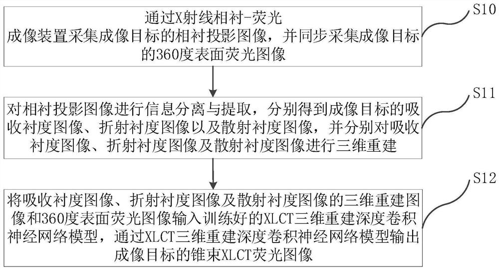
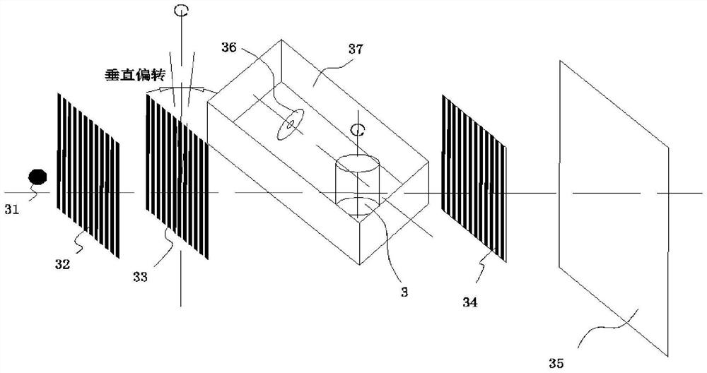
[0039] In view of the deficiencies in the prior art, the cone beam X-ray fluorescence imaging method of the embodiment of the present application uses the X-ray phase contrast imaging method to acquire the phase contrast projection image of the imaging target, and simultaneously collects the surface fluorescence information of the imaging target, according to the phase contrast projection image Extract internal information such as the structure, composition, and electron density distribution of the imaging target as prior information for XLCT reconstruction, and then use a deep convolutiona...


PUM


Abstract

The invention relates to a cone-beam X-ray fluorescence imaging method and system, a terminal and a storage medium. The method comprises the following steps: acquiring a phase contrast projection image of an imaging target through an X-ray phase contrast-fluorescence imaging device, and synchronously acquiring a surface fluorescence image of the imaging target; performing information separation and extraction on the phase contrast projection image to obtain an absorption contrast image, a refraction contrast image and a scattering contrast image of the imaging target, and performing three-dimensional reconstruction on the absorption contrast image, the refraction contrast image and the scattering contrast image respectively; inputting the three-dimensional reconstruction images of the absorption contrast image, the refraction contrast image and the scattering contrast image and the surface fluorescence image into the trained XLCT three-dimensional reconstruction deep convolutional neural network model, and outputting a cone beam XLCT fluorescence image of the imaging target through the XLCT three-dimensional reconstruction deep convolutional neural network model. According to the method, the ill-conditioned degree of solving the cone-beam XLCT three-dimensional reconstruction equation can be effectively reduced, and rapid and high-resolution cone-beam X-ray fluorescence imaging is realized.

Description

technical field [0001] The present application belongs to the technical field of optical molecular imaging, and in particular relates to a cone-beam X-ray fluorescence imaging method, system, terminal and storage medium. Background technique [0002] Optical molecular imaging technology is an imaging technology that uses specific molecular probes to emit light, detects optical signals from molecular markers with an optical imaging system, and restores the spatial distribution of molecular probes through algorithm reconstruction to obtain functional images of cells or tissues. . Optical molecular imaging technology is an important technical means for qualitative or quantitative research on the physiological process and pathological change process of living biological tissues at the cellular molecular level. In the past two decades, bio-optical molecular imaging technology has been rapidly developed and applied in the fields of tumor research and biopharmaceuticals. According...

Claims


Application Information

Patent Timeline
Patent Type & Authority Applications(China)
IPC IPC(8): A61B6/03A61B6/00
CPCA61B6/03A61B6/4085A61B6/485A61B6/484A61B6/4035A61B6/5205A61B6/5211A61B6/5235
Inventor 李志成骆荣辉葛永帅梁栋
Owner SHENZHEN INST OF ADVANCED TECH CHINESE ACAD OF SCI
Why Eureka
Try Eureka