Knife rest punching equipment for professional roller skates

A technology for drilling equipment and roller skates, applied in drilling/drilling equipment, metal processing equipment, applications, etc., can solve problems such as being unsuitable for mass production and easy to damage.

Active Publication Date: 2021-09-10
魏荣华
View PDF8 Cites 0 Cited by
  • Summary
  • Abstract
  • Description
  • Claims
  • Application Information

AI Technical Summary

Problems solved by technology

[0003] In the production of roller skates, it is necessary to punch the roller skates with a knife holder to facilitate the assembly of the pulleys. Now when the punching equipment is punching the roller skates with a knife holder, it is often necessary to manually fix the skates. The tool holder is made of metal, and the sparks splashed during drilling can easily hurt people, and it is not suitable for the current mass production situation. Therefore, a professional roller skate that can be produced in large quantities and is not easy to hurt people is now developed. Knife holder punching equipment

Method used


Image

  • Knife rest punching equipment for professional roller skates
  • Knife rest punching equipment for professional roller skates
  • Knife rest punching equipment for professional roller skates

Examples


Embodiment 1

[0025] A professional wheel skating shoe with tool holder, such as figure 1 , figure 2 , image 3 with Image 6 As shown, including a bottom plate 1, a shelf 2, a drill bobbin 3, a drill 4, a cylinder frame 5, a non-standard gas cylinder 6, a block 7, a placement plate 8, a discharge mechanism 9, a retracting mechanism 10, and a mounting device 13, a bottom plate. 1 is provided with a shelf 2, and the upper portion of the shelf 2 is provided with a drill 4, and the drill frame is uniformly provided with a drill 4. The top of the shelf 2 is provided with a cylinder frame 5, and the cylinder frame 5 is provided with a non-standard cylinder 6, non-standard gas cylinder 6. The bottom and the cylinder frame 5 are connected, and the block 7 is provided on the right side of the drill bit 3, and the shelf 2 is provided with a plate 8, and the rear side of the plate 8 is provided with a discharge mechanism 9, and the lower portion of the shelf 2 is provided 13, shelf 2 The retracting mechani...

Embodiment 2

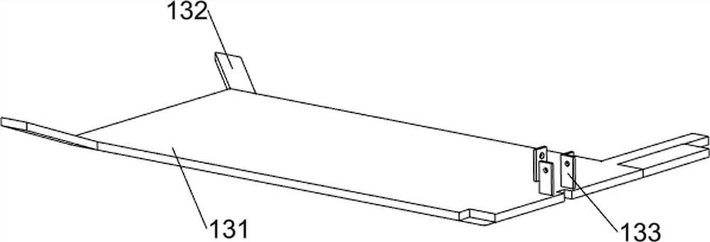
[0031] On the basis of Example 1, such as Figure 4 , Figure 5 with Figure 7 Shown, further comprising a feed mechanism 11, the feed mechanism 11 comprises a bevel gear set 111, a second shaft 112, spur gear 113, the third rack gear 114, a second guide rail 115, the second connecting rod 116, the third spring 117, the slider 118, 131 at the top right side of the guide post 119, the push plate 1110 and support frame 1111, a second mounting plate provided with guide rail 115, a third rack gear slidably connected to the guide rail 114 on the second 115, third tooth Article 114 is provided with a rear side of the second connecting rods 116, two rear gears rotatably supporting connection with a second shaft 112 between 133, 112 is provided with a second spur gear 113 on the shaft, a second shaft 112 and the right connected to a bevel gear set 111, bevel gear set 111 is formed by two bevel gears between the rear side of a shaft 106, two bevel gears are connected to the right rear side of...


PUM


Abstract

The invention relates to punching equipment, in particular to knife rest punching equipment for professional roller skates. The technical problem of the invention is to provide the knife rest punching equipment for the professional roller skates, which can realize mass production and is not easy to hurt people. The knife rest punching equipment for professional roller skates comprises a bottom plate, a frame, a drill bit frame, electric drills, an air cylinder frame, a non-standard air cylinder, a pressing block and a placing plate. The frame is arranged on the bottom plate, the drill bit frame is arranged on the upper portion of the frame, the electric drills are evenly arranged on the drill bit frame, the air cylinder frame is arranged on the top of the frame, the non-standard air cylinder is arranged on the air cylinder frame, and the bottom of the non-standard air cylinder is connected with the air cylinder frame. The pressing block is arranged on one side of the drill bit frame. The placing plate is arranged in the middle of the frame. Through cooperation of the discharging mechanism, the material returning mechanism and the mounting device, the roller skates can be drilled, meanwhile, the roller skates can be pushed out, and therefore the roller skates do not need to be manually taken out.

Description

Technical field [0001] The present invention relates to a punching apparatus, and more particularly to a professional wheel skating cutting device. Background technique [0002] Ice movement is also very popular, but most of the water in my country is shorter, and most people choose temporary rental shoes when they want to skate in winter. Special people buy ice skates. Ice skates are also a rim skating shoe. [0003] In the production of wheel skates, it is necessary to punch the wheel skating with a tool holder to facilitate assembly of pulleys, and now the punching equipment can be fixed, and the ice skate shoes often need to be artificially fixed, ice knife shoes. With the tool holder is a metal, splash splashing at the time of punching is easy to hurt people, and it is not applicable to the current state of mass production, so it is now developing a professional wheel skating shoes that can produce mass production and not hurt people. Tripet punching equipment. Inventive co...

Claims


Application Information

Patent Timeline
Patent Type & Authority Applications(China)
IPC IPC(8): A43D8/02A43D111/00A43D119/00B23B41/00B23Q11/10B23Q7/00
CPCA43D8/02A43D111/00A43D119/00B23B41/00B23Q11/10B23Q7/00
Inventor 魏荣华
Owner 魏荣华
Why Eureka
Try Eureka