Low voltage stress and low input current ripple high gain converter and control method

A current ripple and voltage stress technology, which is applied in the direction of converting DC power input to DC power output, adjusting electrical variables, and controlling/regulating systems, can solve the problems of input inductor current stress and large volume, and difficulty in further improving system efficiency. , to achieve the effect of reducing the ripple rate, reducing loss and cost, and improving conversion efficiency

Active Publication Date: 2022-07-26
NANTONG UNIVERSITY
View PDF6 Cites 0 Cited by
  • Summary
  • Abstract
  • Description
  • Claims
  • Application Information

AI Technical Summary

Problems solved by technology

However, like the traditional Boost converter, the current stress and volume of the input inductor are still large, and the power devices are under high voltage stress, making it difficult to further improve the system efficiency

Method used


Image

  • Low voltage stress and low input current ripple high gain converter and control method
  • Low voltage stress and low input current ripple high gain converter and control method
  • Low voltage stress and low input current ripple high gain converter and control method

Examples


Embodiment Construction

[0037] The technical solutions in the embodiments of the present application will be clearly and completely described below with reference to the drawings in the embodiments of the present application. Obviously, the described embodiments are only a part of the embodiments of the present application, rather than all the embodiments. Based on the embodiments in the present application, all other embodiments obtained by persons of ordinary skill in the art without creative efforts shall fall within the protection scope of the present invention.

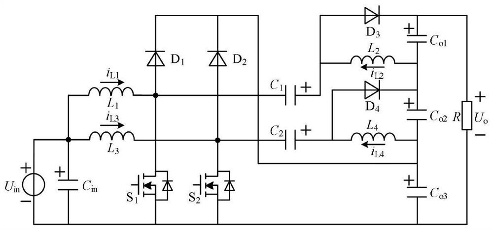
[0038] The invention provides a low voltage stress and low input current ripple high gain converter, the circuit structure is as follows figure 1 shown. The low voltage stress high gain converter includes a DC power supply U in , Input filter capacitor C in , the first inductance L 1 , the second inductance L 2 , the third inductor L 3 , the fourth inductor L 4 , the first switch tube S 1 , the second switch tube S 2 , the first...


PUM

PropertyMeasurementUnit
capacitanceaaaaaaaaaa

Abstract

In the converter disclosed by the invention, the positive pole of the DC power supply is connected to the positive pole of the input filter capacitor and one end of the first and third inductors; the other end of the first inductor is connected to the drain of the first switch tube, the anode of the first diode, and the negative pole of the first capacitor; The other end of the three inductors is connected to the drain of the second switch tube, the anode of the second diode, and the cathode of the second capacitor; the anode of the first capacitor is connected to the anode of the third diode and one end of the second inductor; the cathode of the third diode is connected to the first The anode of the output filter capacitor and one end of the DC load; the cathode of the first output filter capacitor is connected to the other end of the second inductor, the cathode of the fourth diode, and the anode of the second output filter capacitor; the anode of the second capacitor is connected to the anode of the fourth diode and the anode of the fourth diode. One end of the inductor; the negative electrode of the second output filter capacitor is connected to the other end of the fourth inductor, the positive electrode of the third output filter capacitor, and the cathodes of the first and second diodes; the other end of the DC load is connected to the negative electrode of the input filter capacitor, the negative electrode of the third output filter capacitor, the first and second diodes The source of the two switch tubes and the negative pole of the DC power supply.

Description

technical field [0001] The invention belongs to the technical field of DC-DC boost converters, and in particular relates to a low voltage stress and low input current ripple high gain converter and a control method. Background technique [0002] In recent years, non-isolated high-gain converters have been widely used in uninterruptible power systems, renewable energy systems, fuel cells, and hybrid vehicles. In these cases, high-gain converters generally need to have the following characteristics: (1) high voltage gain, sometimes even more than 10; (2) ability to withstand large currents; (3) low input current ripple; ( 4) Under the required volume and quality, it has higher efficiency. [0003] To obtain higher voltage gain, the traditional boost converter needs to work under a very large duty cycle. This produces severe diode reverse recovery losses and EMI, and the system's dynamic characteristics deteriorate. Moreover, under the condition of high duty cycle, the avera...

Claims


Application Information

Patent Timeline
Patent Type & Authority Patents(China)
IPC IPC(8): H02M3/158H02M1/14
CPCH02M3/158H02M1/14
Inventor 秦岭许兴钱天泓张雷徐正祥田民周磊王亚芳段冰莹刘宇涵
Owner NANTONG UNIVERSITY
Why Eureka
Try Eureka