
Laying auxiliary equipment for municipal engineering cable erection

A kind of auxiliary equipment and engineering technology, applied in the direction of cable laying equipment, cable installation, cable installation device, etc., can solve the problems of cumbersome construction, low work efficiency, waste of time and manpower, etc., to improve traction grip and avoid equipment jamming Death, the effect of improving passing performance

Inactive Publication Date: 2021-09-07
滁州旋凯土石方工程有限公司
View PDF8 Cites 2 Cited by
  • Summary
  • Abstract
  • Description
  • Claims
  • Application Information

AI Technical Summary

Problems solved by technology

[0003] The existing cable threading equipment is an ordinary tractor outside the pipe and a manual threading tool. The manual threading tool is composed of a wire feeding tube or a bamboo sheet. The thread end of the cable to be pierced is attached to the threading tool, and the wire feeding tube or Bamboo pieces are fed into the pipe to send the cable ends through the pipe. In the working environment of pipe threading, there are a large number of bent pipes and U-shaped pipes, and there are pipe diameter changes due to corrosion, fatigue damage, cracks, pipe joints, etc. This requires the tiny pipe robot to have a small radial dimension, good passability at bends and U-shaped pipes, and strong adaptability to changing pipe diameters. The traditional threading method cannot cope with it, and the construction is cumbersome and extremely inconvenient. Time and manpower, work efficiency is low, there are certain defects

Method used


Image

  • Laying auxiliary equipment for municipal engineering cable erection
  • Laying auxiliary equipment for municipal engineering cable erection
  • Laying auxiliary equipment for municipal engineering cable erection

Examples


Embodiment Construction

[0027] The following will clearly and completely describe the technical solutions in the embodiments of the present invention with reference to the accompanying drawings in the embodiments of the present invention. Obviously, the described embodiments are only some, not all, embodiments of the present invention. Based on the embodiments of the present invention, all other embodiments obtained by persons of ordinary skill in the art without making creative efforts belong to the protection scope of the present invention.

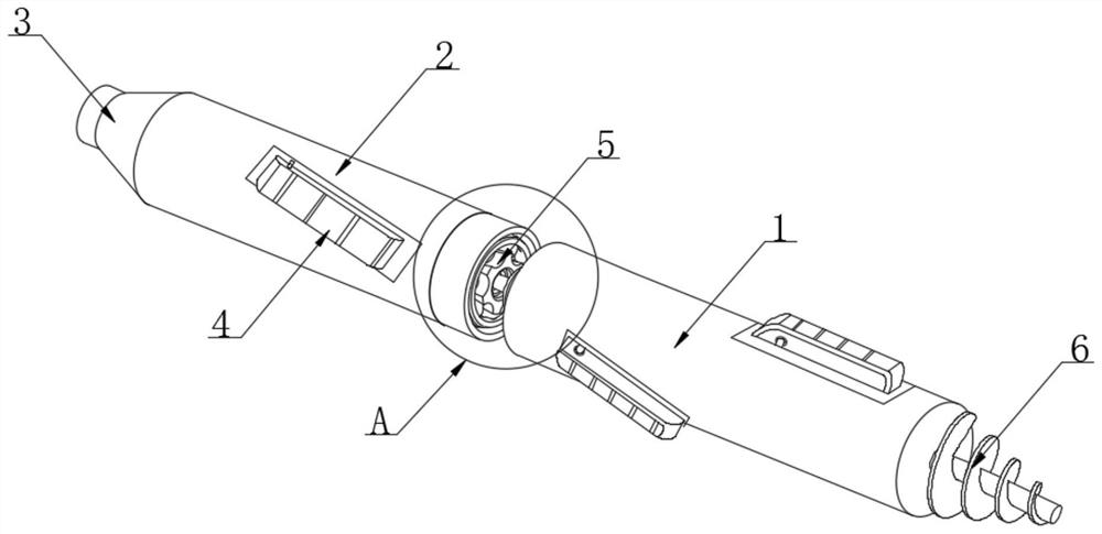
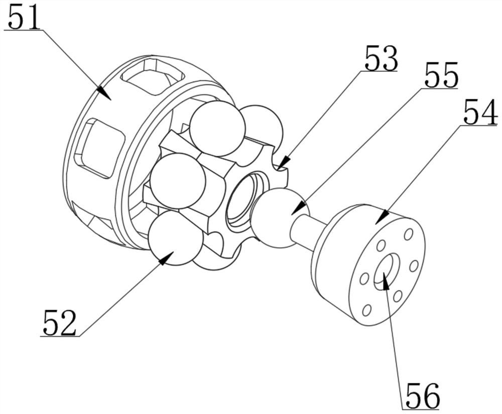
[0028] as attached figure 1 to attach Figure 7 An embodiment of the present invention provides a kind of laying auxiliary equipment for municipal engineering cable erection, including a traction main rod 1 and a booster rod 2. The relative inner side of the push rod 2 is provided with a universal connection node 5, and the surface of the traction main rod 1 and the booster rod 2 is embedded with a power track wheel 4, and one end of the traction main rod 1 i...


PUM

PropertyMeasurementUnit
Lengthaaaaaaaaaa

Abstract

The invention discloses laying auxiliary equipment for municipal engineering cable erection, and particularly relates to the field of municipal engineering. The laying auxiliary equipment comprises a traction main rod and a boosting rod. A pilot line fixing end is fixedly installed at one end of the boosting rod. Universal connection nodes are arranged on the opposite inner sides of the traction main rod and the boosting rod. Power covering wheels are installed on the surfaces of the traction main rod and the boosting rod in an embedded mode. A universal tunneling mechanism is fixedly installed at one end of the traction main rod, and a node sleeve seat is fixedly installed at the end of the boosting rod. According to the scheme, the cable erection auxiliary equipment adopts a sectional type traction machine structure, the traction main rod and the boosting rod are used for power driving and dragging of a cable guide rope to penetrate through a pipeline, in the dragging process, the universal connection of the traction main rod and the boosting rod is achieved through the universal connection nodes, the equipment can pass through bent pipes and U-shaped pipes under the severe working condition of a variable pipe diameter due to corrosion, fatigue damage, cracks, pipe joints and the like, so that the equipment is prevented from being stuck, and the passing performance of the equipment is improved.

Description

technical field [0001] The invention relates to the technical field of municipal engineering, and more specifically, the invention is a kind of laying auxiliary equipment for cable erection in municipal engineering. Background technique [0002] While my country's economy continues to develop, electricity consumption is also increasing, and the scale of the power grid is also expanding. It is often necessary to replace or add cables that have been laid. Since the cable trench has been laid After completion, the cable trench is narrow, the light is poor, and there is a lot of dust. The traditional method is to lift the concrete cover plates one by one, then put the cables in and arrange them, and finally put the cover plates back in place, which makes the above method consume a lot of manpower , wiring efficiency is low. The current construction workers use the method of threader for wiring. The threader was mainly used for traction on the wall at the beginning, and later deve...

Claims


Application Information

Patent Timeline
IPC IPC(8): H02G1/08
CPCH02G1/088
Inventor 刘红
Owner 滁州旋凯土石方工程有限公司
Learn More