
Multi-body collaborative omnidirectional transfer intelligent robot traction system and method

An intelligent robot and traction system technology, applied in aircraft parts, transportation and packaging, ground installations, etc., can solve the problems of high work intensity of personnel, low efficiency of manual traction operation, and hidden safety hazards.

Pending Publication Date: 2021-09-07
CHINA SHIP DEV & DESIGN CENT
View PDF0 Cites 4 Cited by
  • Summary
  • Abstract
  • Description
  • Claims
  • Application Information

AI Technical Summary

Problems solved by technology

[0007] 1) The turning radius of the aircraft itself limits the transfer work of the aircraft in a narrow area; under the condition of limited ground transfer space, the efficiency of manual traction operation is reduced due to the limitation of the turning radius of the aircraft itself;
[0008] 2) The transfer efficiency is low, and the tractor and its steering space will occupy the transfer space, resulting in the inability to transfer on some congested routes; due to the gradual increase in the number of aircraft, the distance between airport stops may be reduced, and the difficulty of manual traction operations will increase;
[0009] 3) A large number of tractor drivers and guides are required, and the personnel have high work intensity and high mental pressure; manual traction work under continuous high-intensity and overloaded work conditions may bring certain safety hazards

Method used


Image

  • Multi-body collaborative omnidirectional transfer intelligent robot traction system and method
  • Multi-body collaborative omnidirectional transfer intelligent robot traction system and method
  • Multi-body collaborative omnidirectional transfer intelligent robot traction system and method

Examples


Embodiment Construction

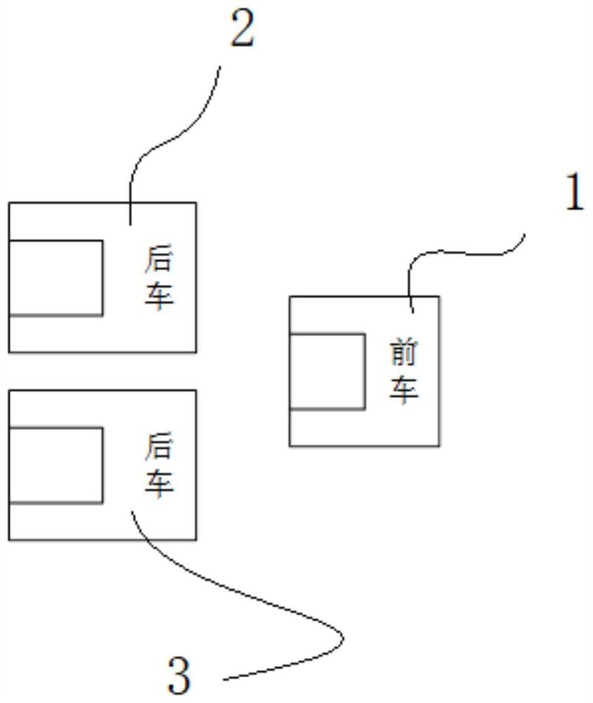
[0049] Attached below Figure 2-14 Taking examples together, the traction system of the multi-body cooperative omnidirectional transfer intelligent robot of the present invention will be described in detail.

[0050] Such as figure 2 , the multi-body collaborative omnidirectional transfer intelligent robot traction system of the present invention is presented by three light-duty omnidirectional intelligent transfer vehicles (including 1 front vehicle 1 and 2 rear vehicles (the first rear vehicle 2 and the second rear vehicle 3) The font layout is combined, the front car 1 is docked with the aircraft front landing gear wheel, and the rear car (the first rear car 2 and the second rear car 3) is docked with the main landing gear wheel.

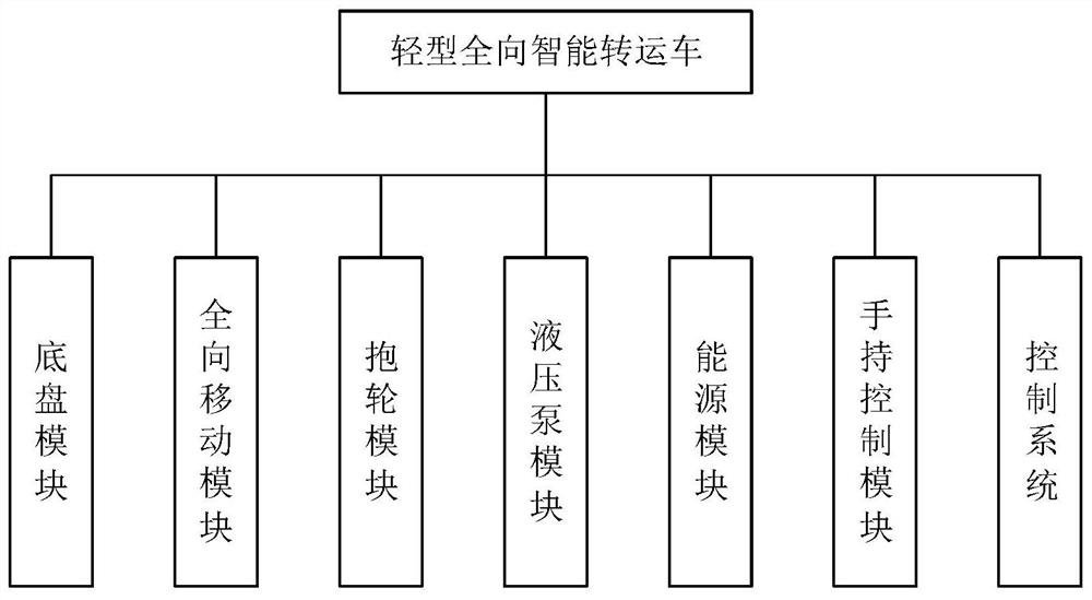
[0051] The structure of the light omnidirectional intelligent transfer vehicle in the multi-body cooperative omnidirectional transfer intelligent robot traction system is basically the same, including the car body or chassis module 6, the omnid...


PUM


Abstract

The invention discloses a multi-body collaborative omnidirectional transfer intelligent robot traction system and method. The system is characterized by comprising three omnidirectional intelligent transfer vehicles which work cooperatively to transfer an airplane, the three omnidirectional intelligent transfer vehicles are arranged and combined in a triangular shape and are not in hard connection with one another, a front vehicle is in butt joint with airplane wheels of a nose landing gear of the airplane, and a rear vehicle is in butt joint with the main undercarriage airplane wheels; the front vehicle is set to receive a control instruction from the main control vehicle, parses path information of each vehicle according to an action instruction, and transmits instruction information to the two rear vehicles, and the three vehicles are in wireless communication; each omnidirectional intelligent transfer vehicle is arranged to lift one airplane wheel of the airplane so as to achieve whole machine lifting and omnidirectional collaborative transfer. The system is mainly applied to aircraft ground traction transfer operation, the flexibility of aircraft traction transfer is improved, accurate traction in-place of the aircraft is conveniently achieved, physical limitations such as the turning radius of the aircraft are broken through, zero-rotation transfer is achieved, and the limited transfer space is better utilized.

Description

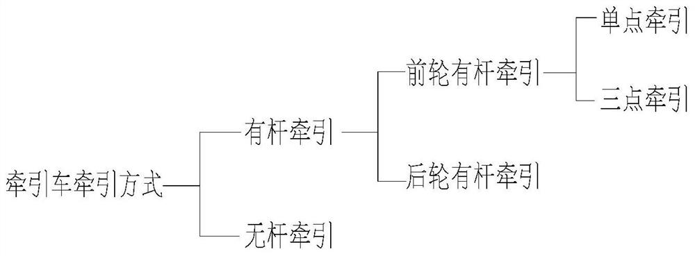
technical field [0001] The invention belongs to the technical field of aircraft ground traction, is mainly used in aircraft ground traction and transfer operations, and relates to a novel omnidirectional transfer intelligent tractor and a traction method suitable for aircraft ground transfer at airports. Background technique [0002] Aircraft tractor is a special vehicle used to transfer aircraft. Using tractor to tow and transfer aircraft can reduce the wear of aircraft engine, save aircraft fuel, reduce noise and exhaust pollution, compared with taxiing by the aircraft's own power. as attached figure 1 As shown, the existing tractors can be divided into two types according to the difference of the traction mode: rod and rodless, and rod traction can be divided into front wheel rod traction and rear wheel rod traction. [0003] (1) Rod tractor: The rod tractor uses the tow bar to tow the aircraft. The rod towing method is a more traditional traction method. For the aircra...

Claims


Application Information

Patent Timeline
Patent Type & Authority Applications(China)
IPC IPC(8): B64F1/22
CPCB64F1/228B64F1/227
Inventor 黄琦王云童剑谢军伟张伟
Owner CHINA SHIP DEV & DESIGN CENT
Learn More