Movable car roof ladder applied to heavy public service rail car

A rail car and movable technology, which is applied in the direction of railway car body components, transportation and packaging, etc., can solve the problems of insufficient space for electrical cabinets and brake cabinets, affecting the opening of electrical cabinet doors, and insufficient height of car body assembly, etc., to achieve good results. Practical application value, avoid redesign, easy to take off and hang the effect

Pending Publication Date: 2021-09-07
CRRC YONGJI ELECTRIC CO LTD
View PDF0 Cites 0 Cited by
  • Summary
  • Abstract
  • Description
  • Claims
  • Application Information

AI Technical Summary

Problems solved by technology

The disadvantages are as follows: 1) When the railcar adds resistance braking, the distance between the resistance braking cabinet and the electrical cabinet is 450mm
The width of the ladder is 320, and the distance between the sides and the electrical cabinet is too small, which affects the opening of the electrical cabinet door, inspection and maintenance
2) Change the distance from 150mm to the wall to 90mm. The distance between the step and the wall is too small. When stepping on the ladder, you can only step on the step with the front of your foot, which does not meet the safety regulations.
[0004] The second prior art is a roof ladder with a shrinkable structure, which has the following disadvantages: 1) The structural width of the ladder is large, and the space between the electrical cabinet and the brake cabinet in the car body is not enough; 2) The height after shrinking is too high, and the car The assembly height in the body is not enough; 3) In addition, the shrunken box body is large and the width is too wide. After the ladder is opened, it is lower than the height of the electrical cabinet, and the space between the electrical cabinet and the brake cabinet in the car body is not enough

Method used


Image

  • Movable car roof ladder applied to heavy public service rail car
  • Movable car roof ladder applied to heavy public service rail car
  • Movable car roof ladder applied to heavy public service rail car

Examples


Embodiment Construction

[0024] Specific embodiments of the present invention will be described in detail below in conjunction with the accompanying drawings.

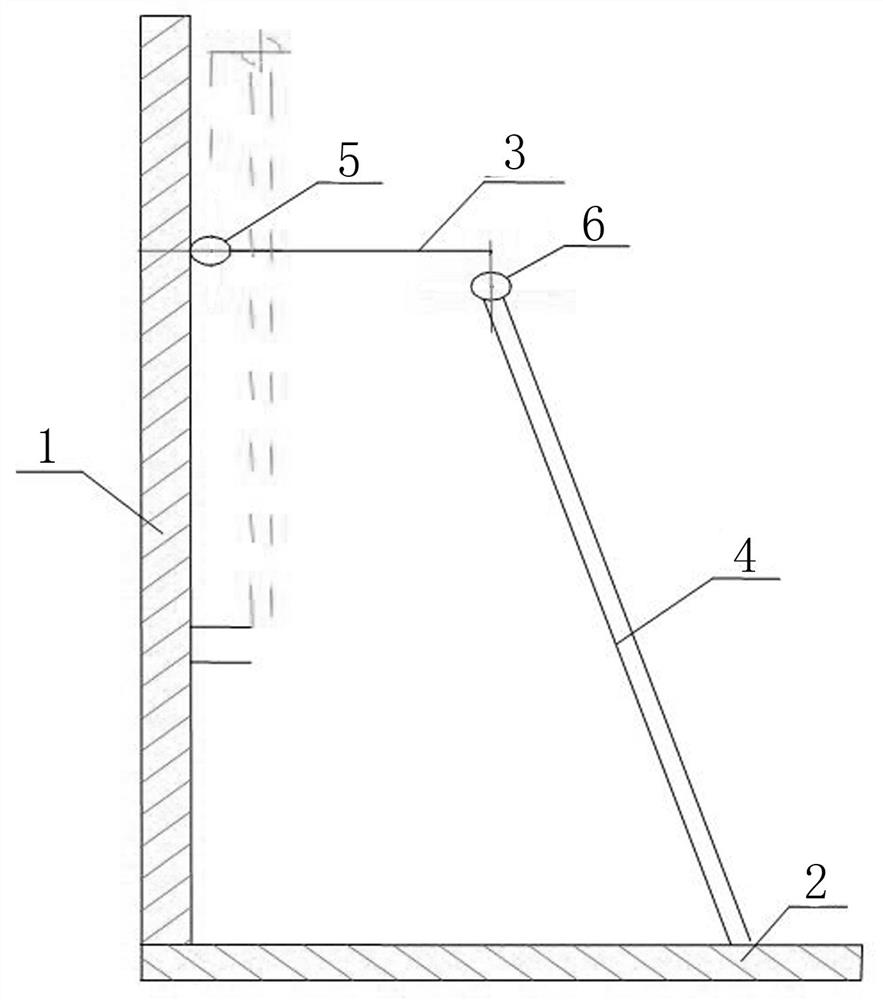
[0025] A movable roof ladder applied to heavy-duty public works rail cars, comprising a pedal 3 and a roof ladder 4.

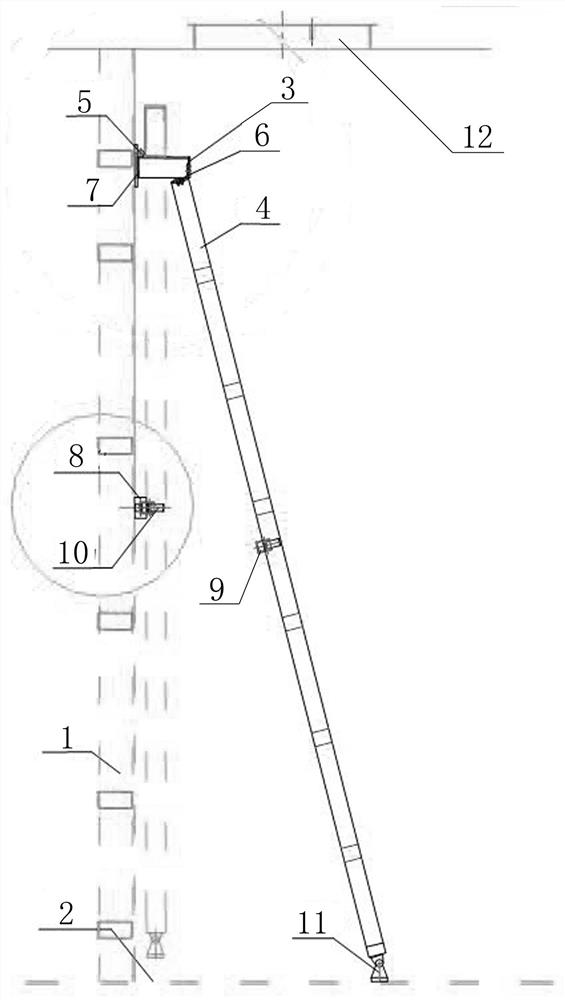
[0026] Such as figure 2 , 3 As shown, the pedal 3 is installed on the partition wall 1 through the hinge 5, and the backing plate I7 ​​is installed on the partition wall 1 at the hinge 5. When the pedal 3 is in use, it is perpendicular to the partition wall 1 and leans against the backing plate I7. When in use, it is parallel to the partition wall 1; that is, the pedal 3 rotates clockwise to a horizontal state during use, and the pedal 3 rotates counterclockwise to a vertical state after use.

[0027] Such as figure 2 , 3 As shown, the end of the pedal 3 is connected to the upper end of the roof ladder 4 through the hinge 6. When the roof ladder 4 is in use, its lower end is supported on the floor 2 at an angle. When the...


PUM


Abstract

The invention discloses a movable car roof ladder applied to a heavy public service rail car. The movable car roof ladder comprises a pedal (3) and a car roof ladder body (4). The pedal (3) is installed on the dividing wall (1) through a hinge (5), the pedal (3) is perpendicular to the dividing wall (1) when in a use state, and the pedal (3) is parallel to the dividing wall (1) when in a non-use state; the end part of the pedal (3) is connected with the upper end of the roof ladder (4) through a hinge (6), the lower end of the roof ladder (4) is supported on the floor (2) at an angle when the roof ladder (4) is in a use state, and the roof ladder (4) is parallel to the dividing wall (1) when the roof ladder (4) is in a non-use state. According to the movable roof ladder designed by the invention, the lower end is quickly pulled open when a user climbs a roof, so that the user can climb the roof conveniently and effortlessly. When not in use, the lower end quickly moves towards the wall, is close to the wall and is hung on the wall, opening and closing of a door of the electric appliance cabinet are not affected, and safety and reliability are achieved.

Description

technical field [0001] The invention relates to the technical field of rail cars for public works, in particular to a movable roof ladder used by crew members to climb on the top of the rail car from inside the car body. Background technique [0002] The heavy-duty public rail car is mainly used for the transportation of construction materials and personnel during railway construction and line maintenance. It is very suitable for traction of maintenance trains, with a maximum operating speed of 120km / h. At the same time, it has power frequency power generation function and supporting power supply facilities, which can provide 150KVA, AC400V, 50Hz three-phase AC power supply for railway construction and connected vehicles. With the rapid development of railway tracks and the continuous improvement of speed, various railway bureaus have continuously increased their technical requirements for railway cars. Various equipment such as transportation monitoring, communications (ant...

Claims


Application Information

Patent Timeline
Patent Type & Authority Applications(China)
IPC IPC(8): B61D23/02
CPCB61D23/02
Inventor 刘修建潘变雒焕骥王青海
Owner CRRC YONGJI ELECTRIC CO LTD
Why Eureka
Try Eureka