
Metal support lug tapping processing device

A processing device and metal technology, which is applied in the field of parts processing devices, can solve problems such as insufficient use effect, low safety, and affecting the quality of equipment use.

Pending Publication Date: 2021-09-07
ANHUI ZHONGGONG TECH
View PDF0 Cites 0 Cited by
  • Summary
  • Abstract
  • Description
  • Claims
  • Application Information

AI Technical Summary

Problems solved by technology

[0003] At present, when the tapping processing device is used, it is necessary to tap the outer surface of the component. For this purpose, a die needs to be used. However, the existing tapping processing device will generate a large amount of Iron filings, and the iron filings will rotate with the rotation of the die, so that the iron filings will be thrown out, which may be thrown into people's eyes, which will make the safety of the device use low, and the thrown iron filings will be thrown out. The crumbs are not convenient for the staff to clean, which affects the quality of the equipment, and the use effect is not good enough. Therefore, we need a metal lug tapping processing device

Method used


Image

  • Metal support lug tapping processing device
  • Metal support lug tapping processing device
  • Metal support lug tapping processing device

Examples


Embodiment 1

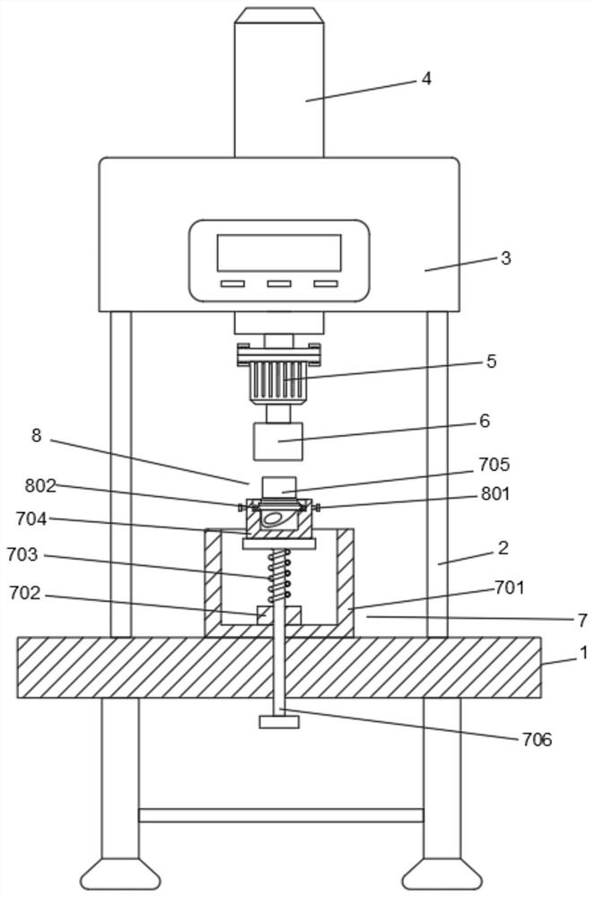
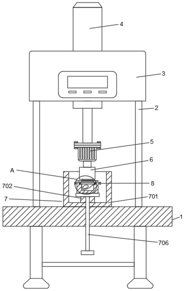
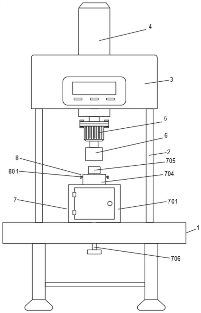
[0024] A metal lug tapping processing device, comprising a platform 1, a vertical support frame 2 is fixedly connected to the top of the platform 1, a body 3 is installed on the top of the support frame 2, a telescopic cylinder 4 is fixedly mounted on the top of the body 3, and the telescopic cylinder The telescopic end of 4 is fixedly connected with motor 5 positioned at the bottom of body 3 , the output end of motor 5 is fixedly connected with die 6 , the top of platform 1 is fixed with receiving mechanism 7 , and fixing mechanism 8 is arranged in receiving mechanism 7 .

[0025] In this embodiment, a controller is fixed on the outer wall of the body 3, and the output end of the controller is connected to the telescopic cylinder 4 and the motor 5. The model of the controller is KY02S, and the telescopic cylinder 4 and the motor 5 are controlled by the controller to improve Efficiency of equipment usage.

Embodiment 2

[0027] A metal lug tapping processing device, on the basis of Embodiment 1, the storage mechanism 7 includes a storage bin 701 installed on the top of the platform 1, a stable block 702 is fixed on the bottom inner wall of the storage bin 701, and the stability block 702 There is a vertically movable stopper 708 running through the inside, and a vertically movable limit rod 706 runs through the inside of the platform 1. The outer surface of the limit rod 706 is covered with a spring 703 located inside the storage bin 701. A fixed plate is fixed, and a placing bin 704 is fixed on the upper part of the fixing plate, and a spring 703 is connected between the fixing plate and the stabilizing block 702 , and a workpiece 705 is placed inside the placing bin 704 .

[0028] In this embodiment, the fixing mechanism 8 includes a threaded sleeve 803 installed on the storage bin 704. The internal thread of the threaded sleeve 803 is connected to a screw 801 in rotation, and the end of the ...


PUM


Abstract

The invention discloses a metal support lug tapping processing device, and relates to the field of part processing. Aiming at the problems that existing scrap iron can be thrown outwards and is inconvenient for workers to clean, the invention provides the following scheme that the metal support lug tapping processing device comprises a platform, wherein a vertical support frame is fixedly connected to the top of the platform; a machine body is installed at the top end of the support frame; a telescopic air cylinder is fixedly installed at the top of the machine body; the telescopic end of the telescopic air cylinder is fixedly connected with a motor located below the machine body; the output end of the motor is fixedly connected with a threading die; a storage mechanism is fixed to the top of the platform; and a fixing mechanism is arranged in the storage mechanism. According to the device, scrap iron generated by tapping can be collected while tapping is conducted, and later treatment is facilitated, so that use convenience can be brought to a user; and the whole device is simple in structure and low in manufacturing cost.

Description

technical field [0001] The invention relates to the field of parts processing devices, in particular to a metal lug tapping processing device. Background technique [0002] Thread processing is a process of processing workpieces using cutting, turning, milling, grinding and other processes using tools for making threads. It generally refers to the method of processing threads on workpieces with forming tools or abrasive tools, while tapping refers to It is to use a certain torque to screw the tap into the bottom hole to be drilled to process the internal thread. [0003] At present, when the tapping processing device is used, it is necessary to tap the outer surface of the component. For this purpose, a die needs to be used. However, the existing tapping processing device will generate a large amount of Iron filings, and the iron filings will rotate with the rotation of the die, so that the iron filings will be thrown out, which may be thrown into people's eyes, which will ...

Claims


Application Information

Patent Timeline
IPC IPC(8): B23G1/00B23G1/44
CPCB23G1/00B23G1/44
Inventor 张玉喜齐咏
Owner ANHUI ZHONGGONG TECH
Learn More