Adjustable and controllable delay circuit, delay circuit system and method
A delay circuit and control circuit technology, which is applied in the field of delay circuit systems and adjustable delay circuits, can solve problems such as difficult implementation, complicated power sequence control design, and failure of integrated circuits to operate normally, and achieve difficult and costly design. Effect
- Summary
- Abstract
- Description
- Claims
- Application Information
AI Technical Summary
Problems solved by technology
Method used
Image
Examples
Embodiment 1
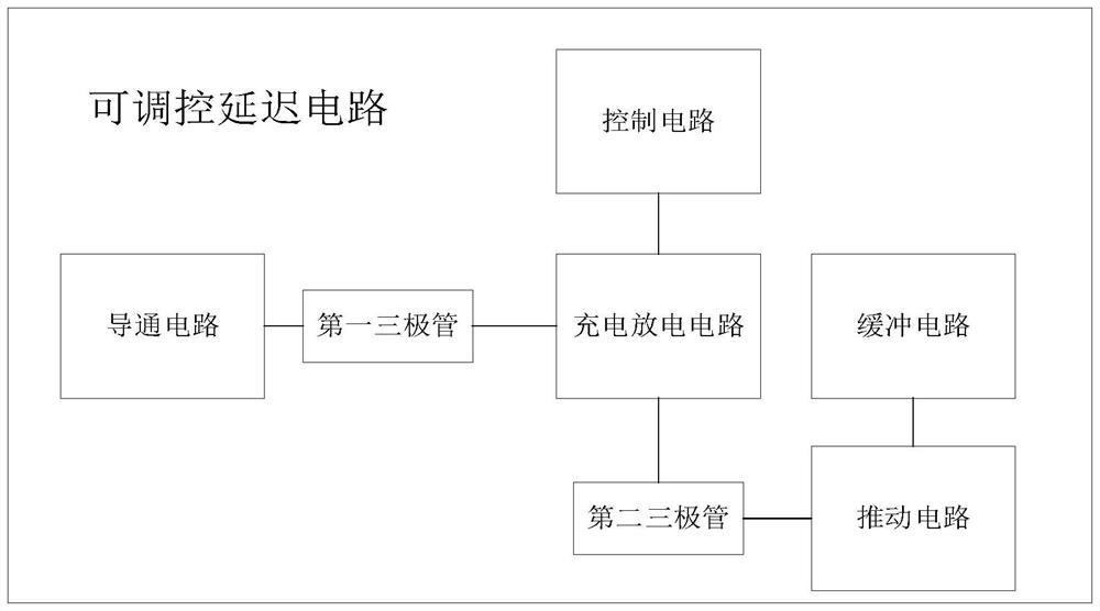
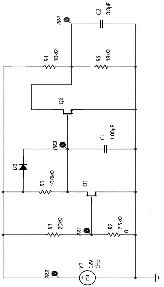
[0071] Embodiments of the present invention provide an adjustable delay circuit, see figure 1 with figure 2 , Including: conductive circuitry, control circuitry, charge discharge circuit, driving circuit, and buffer circuit;
[0072] The conduction circuit is connected to the charging discharge circuit by the first NPN triode Q1; the guiding circuit is used to trigger the required voltage to be turned on, for implementing the delay integrated circuit to monitor the outside. Voltage to make enabled function;
[0073] The charging discharge circuit is connected to the control circuit;
[0074] The control circuit selects the operating state of the control circuit according to the state of the first NPN triode Q1;
[0075] When the trigger state of the first NPN triode Q1 is a trigger state, the control circuit is used to accelerate the charging time of the charging discharge circuit;
[0076] When the trigger state of the first NPN triode Q1 is inverted, the control circuit is an in...
Embodiment 2
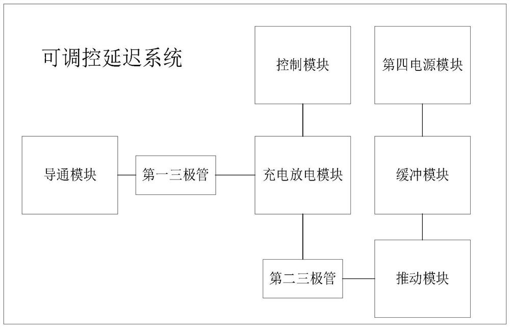
[0111] One of the above-mentioned modulatled delay circuits is a perspective from a hardware circuit, and the embodiment of the present invention further provides an adjustable delay system, and is a perspective of a functional module, see image 3 , Including: turn-on module, control module, charging discharge module, push module, buffer module, and fourth power module;
[0112] The conduction module is connected to the charging discharge module via the first NPN triode; the turning module is used to control the voltage of the first NPN triode; the charging discharge module is used to perform RC discharge;
[0113] The charging discharge module is connected to the control module; the control module is used to select a working state according to the status of the first NPN triode;
[0114] The charging discharge module is connected by a second NPN triode and a push module; the push module is connected to the fourth power module by the buffer module;
[0115] The push module is used...
Embodiment 3
[0121] Embodiments of the present invention also provide an adjustable delay method, please refer to Figure 4 , Including the following steps:
[0122] S100, set on resistance, first NPN triode, first diode D1, RC circuit, and buffer control circuitry;
[0123] S200, through the conductive resistance and the first NPN triode monitor and control the external power supply for enabling;
[0124] The specific step is: by selecting the resistance of the on-resistance to control the voltage of the first NPN triode, and then monitor and control the external power supply through the first NPN triode;
[0125] S300, controls the working state of the first diode D1 according to the state of the first NPN triode;
[0126] The specific step is: When the state of the first NPN triode is on state, the working state of the first diode D1 is the charging time of the accelerated capacitor;
[0127] When the state of the first NPN triode is not in-state, the working state of the first diode D1 is n...
PUM
 Abstract
Description
Claims
Application Information
 - R&D
- Intellectual Property
- Life Sciences
- Materials
- Tech Scout
- Unparalleled Data Quality
- Higher Quality Content
- 60% Fewer Hallucinations
Browse by: Latest US Patents, China's latest patents, Technical Efficacy Thesaurus, Application Domain, Technology Topic, Popular Technical Reports.
© 2025 PatSnap. All rights reserved.Legal|Privacy policy|Modern Slavery Act Transparency Statement|Sitemap|About US| Contact US: help@patsnap.com


