UPS emergency power supply for industrial power and power supply method thereof

A technology of emergency power supply and electric power, applied in emergency power supply arrangement, battery circuit device, circuit, etc., can solve the problems of damage to the original power supply of emergency power supply, unfavorable emergency power supply power supply, easy sparks in connection, etc., to reduce the probability of breakage and easy to solve. Damage, short-circuit prevention effect

Active Publication Date: 2021-09-03
常州市信宝电源设备有限公司
View PDF3 Cites 0 Cited by
  • Summary
  • Abstract
  • Description
  • Claims
  • Application Information

AI Technical Summary

Problems solved by technology

[0003] In the prior art, wherein the publication number is CN208444896U discloses a multifunctional emergency power supply, which includes a box body, a water battery pack, a lighting control board, a positive terminal, a negative terminal, a lighting module and a control button, the box An installation chamber for accommodating a water battery pack is formed in the lower part, and a water injection port communicated with the installation chamber is provided on the top of the box body. The positive terminal and the negative terminal are respectively fixed on both sides of the top of the box. It can be used by adding water during use, which is very convenient. However, when the charging device is connected to the positive terminal and the negative terminal, due to the discharge phenomenon of the emergency power supply, sparks are prone to occur during connection, causing damage to the original emergency power supply. , is not conducive to the power supply of the emergency power supply, and at the same time, it is inconvenient to operate the positive terminal and the negative terminal when fixing the charging connection. Therefore, a UPS emergency power supply for industrial power and its power supply method are proposed.

Method used


Image

  • UPS emergency power supply for industrial power and power supply method thereof
  • UPS emergency power supply for industrial power and power supply method thereof
  • UPS emergency power supply for industrial power and power supply method thereof

Examples


Embodiment 1

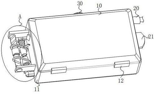
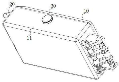
[0040] Embodiment 1: According to Figure 1-Figure 6 and Figure 11 As shown, a UPS emergency power supply for industrial power includes an upper casing 10, a lower casing 11, and a connection block 12. A battery block 111 is installed inside the lower casing 11, and the left side of the battery block 111 is front and rear. Both terminals are fixedly connected with a terminal block 14, and the outer surface of the terminal block 14 is fixedly connected with a hexagonal block 144, which is a common spacer for an existing terminal post, and the two terminal blocks 14 both extend to the lower casing 11 The outer side of the terminal block 14 at the front end is fixedly connected with a positive terminal 141, and the end of the terminal block 14 at the rear end is fixedly connected with a negative terminal 145, and the hexagonal block 144 is connected to the corresponding positive terminal 141 is in contact with the end of the negative pole terminal 145, and the setting of the he...

Embodiment 2

[0042] Embodiment 2: On the basis of Embodiment 1, a control switch 15 is installed on the left rear portion of the lower housing 11, and the end of the slider 132 close to the control switch 15 is fixedly connected with a push block 133. The switch 15 is rotatably connected with the lower housing 11. The material of the end of the push block 133 away from the slider 132 is made of rubber, and the end of the push block 133 in contact with the control switch 15 is made of rubber to protect the control switch 15. The push block 133 can push the control switch 15 during the sliding process, so that the push block 133 can push the control switch 15 to realize the power supply control of the emergency power supply, and the control switch 15 of the emergency power supply and the positive pole terminal 141 and the negative pole The movement distance of the cover block 142 on the terminal 145 is related, so that the control switch 15 is in the state of controlling the emergency power s...

Embodiment 3

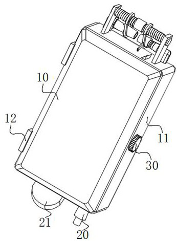
[0044] Embodiment 3: on the basis of embodiment 1 and embodiment 2, according to figure 1 , Figure 9 and Figure 15 As mentioned above, the right side of the lower case 11 is fixedly connected with a hollow column 20, and the right side of the battery block 111 is equipped with a power line, and the power line extends to the outside of the lower case 11 through the hollow column 20, so The hollow column 20 is designed in the shape of a truncated cone. The hollow column 20 arranged in the shape of a truncated cone is a hollow structure. The side of the hollow column 20 arranged in the shape of a truncated cone is in contact with the lower casing 11. Therefore, the power cord extends to the lower casing 11. After the outer side, the active area of ​​the power line increases on the basis of achieving stability, which can effectively prevent the power line from breaking, reduce the short circuit phenomenon of the emergency power supply, and facilitate the power supply of the eme...


PUM


Abstract

The invention provides a UPS emergency power supply for industrial power and a power supply method thereof. The industrial power UPS emergency power supply comprises a lower shell, a battery block, a positive terminal and a negative terminal, the positive terminal and the negative terminal are mounted at the end of the battery block, the battery block is mounted in the lower shell, and the positive terminal and the negative terminal are mounted on the outer side of the lower shell. Outer side walls of the positive terminal and the negative terminal are uniformly provided with external threads. The emergency power supply further comprises an adjusting mechanism, the adjusting mechanism comprises a two-way threaded rod and sleeve blocks, the two-way threaded rod is rotatably connected with the lower shell, and the two sleeve blocks are slidably connected with the two-way threaded rod. By arranging the bidirectional threaded rod on the emergency power supply, the movement of the sleeve blocks used for fixing the joint of the charging equipment on the positive terminal and the negative terminal on the emergency power supply can be controlled, so that the emergency power supply and the positive and negative electrodes of the charging equipment are simultaneously connected, and the time required for connecting the charging equipment and the emergency power supply is shortened; and the use efficiency of the emergency power supply in the practical application process is improved.

Description

technical field [0001] The invention relates to an emergency power supply, in particular to a UPS emergency power supply for industrial power and a power supply method thereof. Background technique [0002] UPS is an uninterruptible power supply, which is set up to solve uninterrupted power supply. It connects the battery with the host, and converts direct current into mains system equipment through module circuits such as the host inverter. The emergency power supply and UPS emergency power supply are important nowadays. In buildings, an emergency power supply is used for emergency lighting, accident lighting, and fire-fighting facilities. It is mainly composed of input units, output units, charging modules, battery packs, inverters, monitors, and output switching devices. The system can provide emergency power supply under emergency conditions. [0003] In the prior art, wherein the publication number is CN208444896U discloses a multifunctional emergency power supply, whi...

Claims


Application Information

Patent Timeline
Patent Type & Authority Applications(China)
IPC IPC(8): H02J7/00H01R9/00H02J9/06
CPCH02J7/0045H02J7/0063H01R9/00H02J9/062
Inventor 高银芬
Owner 常州市信宝电源设备有限公司
Why Eureka
Try Eureka