Charging circuit, control method of charging circuit, controller of charging circuit and charging pile

A technology of charging circuit and control method, which is applied in the direction of charging/discharging current/voltage regulation, battery circuit device, charging station, etc., can solve the problem of small working temperature range, achieve the effect of increasing the working temperature range and improving the working stability

Pending Publication Date: 2021-09-03
SUNGROW POWER SUPPLY CO LTD
View PDF0 Cites 0 Cited by
  • Summary
  • Abstract
  • Description
  • Claims
  • Application Information

AI Technical Summary

Problems solved by technology

[0004] The main purpose of the present invention is to provide a charging circuit, which aims to solve the problem that the operating temperature range of the full power output of the existing charging circuit is small

Method used


Image

  • Charging circuit, control method of charging circuit, controller of charging circuit and charging pile
  • Charging circuit, control method of charging circuit, controller of charging circuit and charging pile
  • Charging circuit, control method of charging circuit, controller of charging circuit and charging pile

Examples


Embodiment Construction

[0050] The following will clearly and completely describe the technical solutions in the embodiments of the present invention with reference to the accompanying drawings in the embodiments of the present invention. Obviously, the described embodiments are only part of the embodiments of the present invention, not all of them. Based on the embodiments of the present invention, all other embodiments obtained by persons of ordinary skill in the art without creative efforts fall within the protection scope of the present invention.

[0051] In addition, in the present invention, descriptions such as "first", "second" and so on are used for description purposes only, and should not be understood as indicating or implying their relative importance or implicitly indicating the quantity of indicated technical features. Thus, the features defined as "first" and "second" may explicitly or implicitly include at least one of these features. In addition, the technical solutions of the vari...


PUM


Abstract

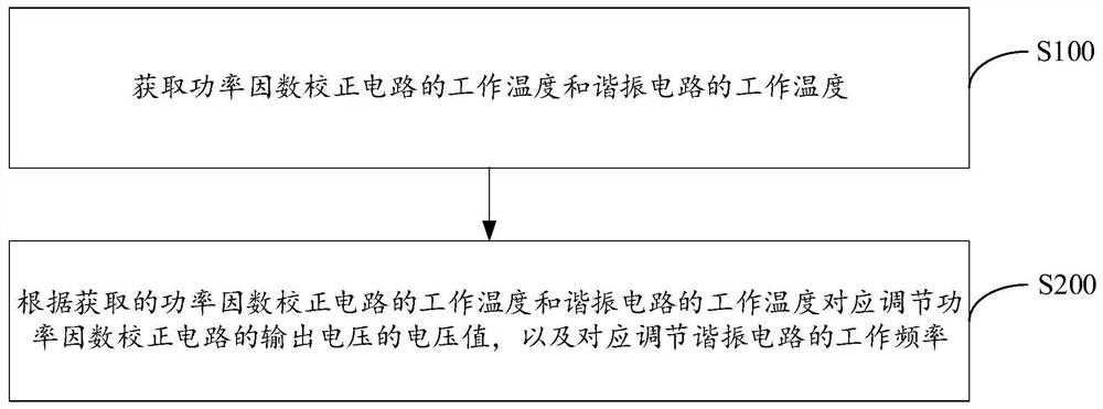
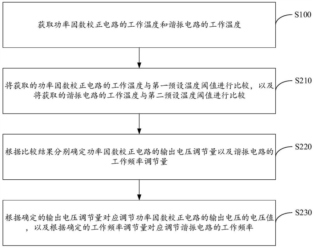
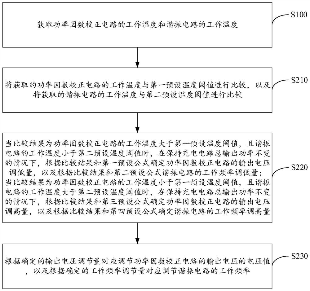
The invention discloses a charging circuit, a control method of the charging circuit, a controller of the charging circuit and a charging pile. The control method of the charging circuit comprises the steps that: the working temperature of a power factor correction circuit and the working temperature of a resonance circuit are acquired; and according to the obtained working temperature of the power factor correction circuit and the working temperature of the resonance circuit, the voltage value of the output voltage of the power factor correction circuit is correspondingly adjusted, and the working frequency of the resonance circuit is correspondingly adjusted. According to the charging circuit, the control method of the charging circuit, the controller of the charging circuit and the charging pile of the technical scheme, the working temperature range of full-power output of the charging circuit can be extended, and the service life of the charging circuit is prolonged.

Description

technical field [0001] The invention relates to the technical field of charging piles, in particular to a charging circuit, a method for controlling the charging circuit, a controller thereof, and a charging pile. Background technique [0002] At present, charging piles often use PFC (power factor correction) circuit and LLC (resonant) circuit to build the charging circuit, but as the charging voltage required by different electric vehicles is different, it is necessary to maintain the charging circuit in a constant power full-range output state , to meet the charging needs of different electric vehicles. [0003] However, in the existing charging circuit, the gain of the back-end LLC circuit is first adjusted to a fixed gain, and then the output voltage of the front-end PFC circuit is controlled to realize the constant power full-range output regulation of the charging circuit. In this way, when the output voltage of the PFC circuit changes, it will cause the power tube of...

Claims


Application Information

Patent Timeline
IPC IPC(8): H02J7/00H02M1/42B60L53/31
CPCH02J7/007H02J7/007192H02M1/4241B60L53/31H02J2207/20Y02T10/70Y02T10/7072Y02T90/12
Inventor 江冯林张杰许林冲
Owner SUNGROW POWER SUPPLY CO LTD
Why Eureka
Try Eureka