Laser detection device, control method thereof, control device and terminal

A technology of laser detection and detection devices, which is applied in the field of sensors and can solve problems such as high prices

Active Publication Date: 2021-08-31
HUAWEI TECH CO LTD
View PDF8 Cites 0 Cited by
  • Summary
  • Abstract
  • Description
  • Claims
  • Application Information

AI Technical Summary

Problems solved by technology

If you want to read the real-time rotation angle to achieve higher accuracy, you need a more precise optical code disc, and as the accuracy of the optical code disc increases, its price becomes more expensive

Method used


Image

  • Laser detection device, control method thereof, control device and terminal
  • Laser detection device, control method thereof, control device and terminal
  • Laser detection device, control method thereof, control device and terminal

Examples


Embodiment Construction

[0055] The technical solution in this application will be described below with reference to the accompanying drawings.

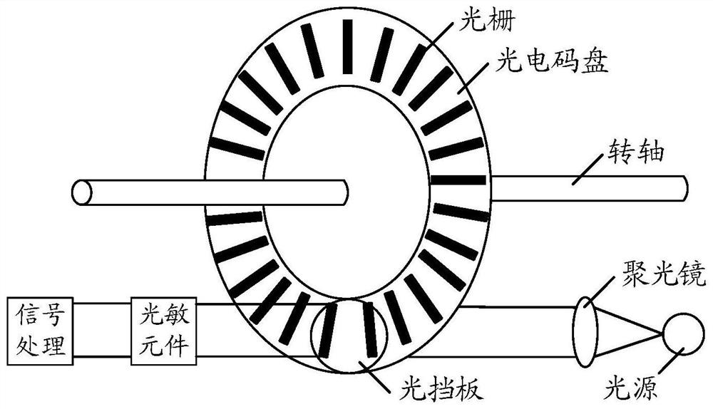
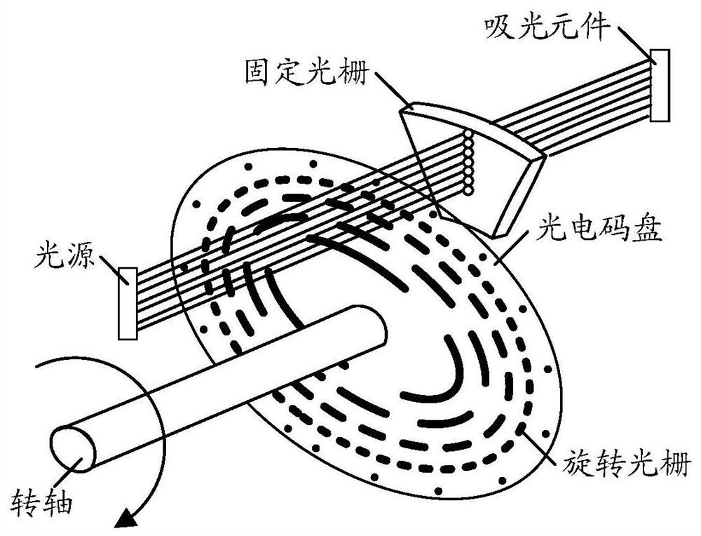
[0056] In the laser radar, the photoelectric encoder installed on the motor that drives the polygon mirror to rotate reads the real-time rotation angle of the polygon mirror. Further, the laser radar uses the photoelectric encoder to read the real-time rotation angle of the polygon mirror to control the lighting timing and synchronization. Point cloud timing. Wherein, the lighting timing can be understood as the timing when the laser emitting unit starts emitting light beams and stops emitting light beams, or can simply be understood as the working timing of the laser emitting unit. The synchronous point cloud timing can be understood as the timing when the laser detection unit starts to receive the reflected beam of the beam emitted by the laser emitting unit, or it can be simply understood as the working timing of the laser detection unit. Therefore, the ...


PUM


Abstract

The invention provides a detection device, a control method of the detection device, a control device and a terminal, which can be applied to the fields of intelligent driving, automatic driving, intelligent manufacturing or surveying and mapping and the like. Besides a laser transceiving module for executing target detection, the detection device is also provided with a reflector and a synchronous transceiving module for realizing a synchronous function. Wherein the reflecting mirror is used for reflecting an emitted light beam from the laser receiving and transmitting module to a detection area and reflecting a reflected light beam from the detection area to the laser receiving and transmitting module. Furthermore, the light beam passing through the reflector is detected through the synchronous transceiving module, high-precision rotation speed measurement and rotation angle measurement of the reflector are realized, the rotation speed of the reflector is adjusted in time, and the detection precision of the detection device is improved. Particularly, in a detection device which is sensitive in cost and high in precision requirement, the cost can be greatly reduced on the premise of ensuring the performance. Specifically, the detection device can be a laser radar.

Description

technical field [0001] The present application relates to sensor technology, and in particular to a detection device, a control method of the detection device, a control device and a terminal. It can be applied to fields such as intelligent driving, automatic driving, intelligent manufacturing, or surveying and mapping. Background technique [0002] A light detection and ranging (Lidar) system is used for distance detection. The laser radar emits laser light to the detection target, and then the receiver collects the light signal reflected by the target, and determines the distance of the target by measuring the round-trip time of the transmitted signal. Because the laser has the advantages of good directionality and monochromaticity, the laser radar system can realize long-distance and high-precision ranging functions. The lidar system extends the ranging result of a single point to two dimensions through scanning or multi-element array detection to form a distance image....

Claims


Application Information

Patent Timeline
IPC IPC(8): G01S17/02G01S7/481
CPCG01S17/02G01S7/481G01S7/4817G01S17/42G01S17/931G01S7/497G01S17/89G01S7/4815
Inventor 韩伟安凯王洪亮
Owner HUAWEI TECH CO LTD
Why Eureka
Try Eureka