Safe intelligent rod with telescopic rod body
A safe and functional technology, applied in the field of smart rods, can solve the problems of easy wear of the tube block, the inability of the tube block to stably contact the outer tube and inner tube, and the shaking of the inner tube
- Summary
- Abstract
- Description
- Claims
- Application Information
AI Technical Summary
Problems solved by technology
Method used
Image

Examples
Embodiment 1
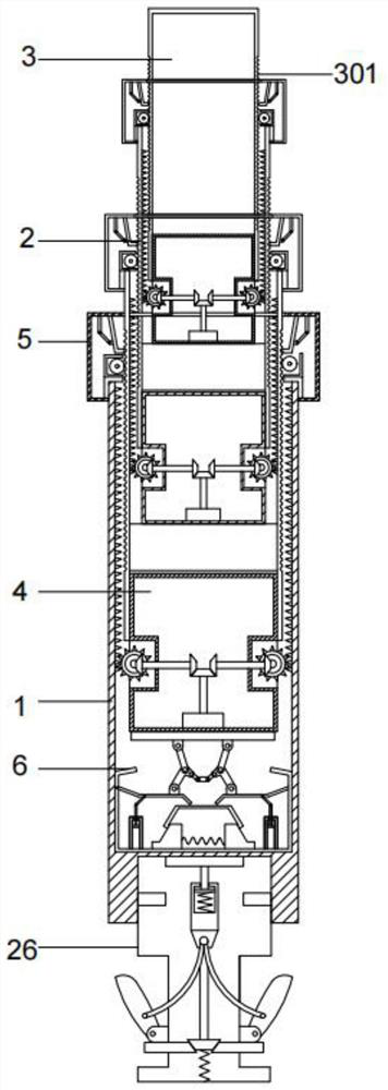
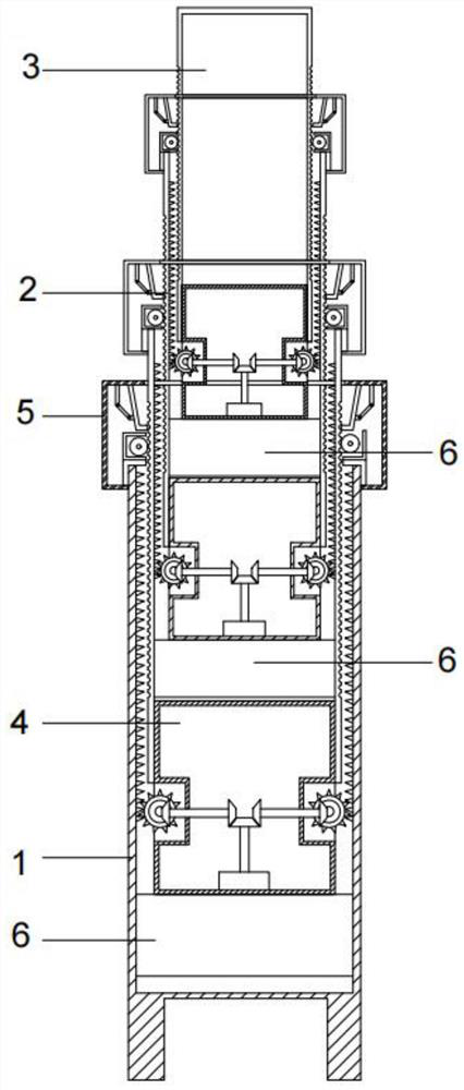
[0058] An embodiment of the present invention provides a safe smart pole with a telescopic function of the pole body, such as Figure 1-Figure 2 As shown, it includes bottom rod 1, several movable rods 2 and ejector rods 3, and the bottom rod 1, several movable rods 2 and ejector rods 3 are sequentially connected from bottom to top, and the inside of the bottom rod 1 and several movable rods 2 Position-limiting mechanisms 6 are respectively provided, and the upper ends of the bottom rod 1 and some movable rods 2 are respectively connected with stabilizing mechanisms 5, and the plurality of movable rods 2 and the ejector rods 3 are respectively connected with a driving mechanism 4, and the inside of the driving mechanism 4 is provided with There is a motor 402 to which a control assembly is connected.
[0059] The beneficial effect of above-mentioned technical scheme is:
[0060] Several movable rods 2 and ejector rods 3 are respectively connected with driving mechanism 4, and...
Embodiment 2
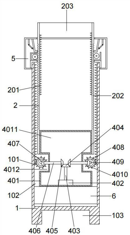
[0062] On the basis of Example 1, such as Figure 1-Figure 3 As shown, the plurality of movable rods 2 are sequentially connected from top to bottom, and the plurality of movable rods 2 are provided with movable chamber two 203 up and down, and the diameter of the movable chamber two 203 inside the movable rod 2 on the lower side is larger than that on the upper side The diameter of the movable rod 2, the left and right sides of the movable chamber 203 are symmetrically provided with racks 2 201, the outer left and right sides of the movable rod 2 are symmetrically provided with a plurality of slots 1 202, and the plurality of card slots 202 are arranged symmetrically. Groove one 202 is arranged at regular intervals along the vertical direction of the movable rod 2;
[0063] The upper end of the bottom rod 1 is provided with a movable chamber one 102, and the diameter of the movable chamber one 102 is greater than the diameter of the movable rod two 2 connected with the bottom...
Embodiment 3
[0067] On the basis of Example 2, such as Figure 2-Figure 3 As shown, the driving mechanism 4 includes a driving housing 401, the upper side of the driving housing 401 is fixedly connected with the lower side of the movable chamber 203 and the inner lower side of the push rod 3, and the driving housing 401 is internally provided with The first cavity 4011, the left and right ends of the driving shell 401 are symmetrically provided with a groove 1 4012, the bottom end of the first cavity 4011 is fixedly provided with the motor 402, and the motor 402 is fixedly connected with a rotating shaft One 403, the first rotating shaft 403 is fixedly connected with the first bevel gear 404, the second bevel gear 405 is symmetrically engaged with the left and right sides of the first bevel gear 404, and the second bevel gear 405 is fixedly connected with the second bevel gear 406, so The second rotating shaft 406 passes through the side end of the first cavity 4011 and enters the inside o...
PUM
 Abstract
Description
Claims
Application Information
 - R&D
- Intellectual Property
- Life Sciences
- Materials
- Tech Scout
- Unparalleled Data Quality
- Higher Quality Content
- 60% Fewer Hallucinations
Browse by: Latest US Patents, China's latest patents, Technical Efficacy Thesaurus, Application Domain, Technology Topic, Popular Technical Reports.
© 2025 PatSnap. All rights reserved.Legal|Privacy policy|Modern Slavery Act Transparency Statement|Sitemap|About US| Contact US: help@patsnap.com