Construction method for on-site segmental pouring type concrete gallery and water storage pond

A construction method and pouring technology, applied in water conservancy projects, artificial islands, waterway systems, etc., can solve problems such as high construction costs and inconvenient construction of concrete containers

Pending Publication Date: 2021-08-31
四川康兴茂环保科技有限公司
View PDF6 Cites 0 Cited by
  • Summary
  • Abstract
  • Description
  • Claims
  • Application Information

AI Technical Summary

Problems solved by technology

[0003] The purpose of the present invention is to provide a construction method for on-site segmental pouring concrete corridors and storage tanks to solve the problems of inconvenient construction and high construction costs of existing concrete containers

Method used


Image

  • Construction method for on-site segmental pouring type concrete gallery and water storage pond
  • Construction method for on-site segmental pouring type concrete gallery and water storage pond
  • Construction method for on-site segmental pouring type concrete gallery and water storage pond

Examples


Embodiment 1

[0039] A construction method for segmental pouring concrete pipe gallery on site, comprising the following steps:

[0040] S1: Excavating a trench, and constructing a concrete floor 10 at the bottom of the trench;

[0041] S2: Construct the pipe gallery unit of the first segment, specifically including the following steps:

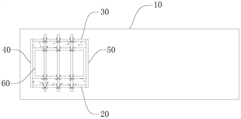
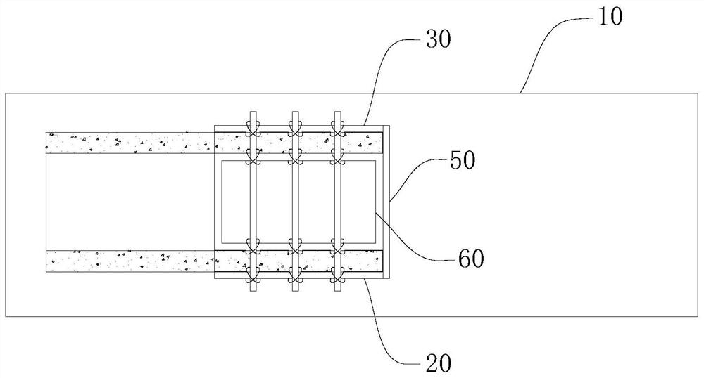
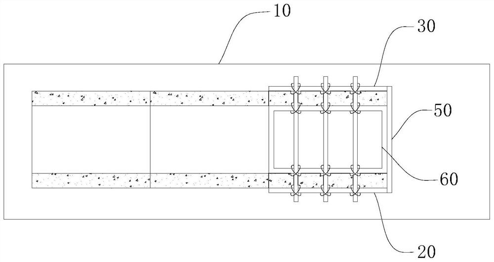
[0042] S21: install the left mold 20 and the right mold 30 and the front mold 40 and the rear mold 50 on the bottom plate 10 through bolts, the left mold 20 and the right mold 30 are arranged in parallel, and the front mold 40 and the rear mold 50 are respectively located The two ends of the left side mold 20 and the right side mold 30, and the plate surface of the front end mold 40 and the rear end mold 50 are in contact with the end faces of the left side mold 20 and the right side mold 30 to form an outer mold;

[0043] S22: Set the prefabricated reinforcement mesh inside the outer form near the base plate 10, the left formwork 20 and the right formwor...

Embodiment 2

[0054] A construction method for a field segmental pouring concrete sewage treatment tank, comprising the following steps:

[0055] S1: Concrete base plate 10 is constructed at the pre-construction position;

[0056] S2: constructing the sewage treatment tank unit of the first segment, specifically including the following steps:

[0057] S21: install the left mold 20 and the right mold 30 and the front mold 40 and the rear mold 50 on the bottom plate 10 through bolts, the left mold 20 and the right mold 30 are arranged in parallel, and the front mold 40 and the rear mold 50 are respectively located The two ends of the left side mold 20 and the right side mold 30, and the plate surface of the front end mold 40 and the rear end mold 50 are in contact with the end faces of the left side mold 20 and the right side mold 30 to form an outer mold;

[0058] S22: Set the prefabricated steel mesh inside the outer mold close to the bottom plate 10, the left mold 20, the right mold 30, t...


PUM


Abstract

The invention discloses a construction method for an on-site segmental pouring type concrete gallery and a water storage pond, and belongs to the technical field of construction. A pipe gallery, a ditch, a water storage tank and a sewage treatment tank are prepared by repeatedly using a combined steel mold, prefabricating the factory-like reinforcing steel bars and cover plates and pouring the concrete on site in sections, so that the construction procedure is simplified, the construction time is shortened, on-site constructors are reduced, the engineering cost is reduced, and a formed product is free of leakage, good in sealing performance and long in service life.

Description

technical field [0001] The invention relates to the field of construction technology, in particular to a construction method for segmentally poured concrete corridors and water storage tanks on site. Background technique [0002] Corridors include pipe galleries and ditches. The pipe gallery is to build a tunnel space underground in the city, integrating various engineering pipelines such as power, communication, gas, heating, water supply and drainage, etc., with special inspection ports, hoisting ports and monitoring systems, implementing unified planning, Unified design, unified construction and management is an important infrastructure and "lifeline" to ensure the operation of the city. A ditch is a channel dug for irrigation or drainage. The cistern is composed of multiple concrete pools arranged in sequence for water storage. The sewage treatment pool belongs to the storage pool, which is composed of multiple concrete pools arranged in sequence, and the sewage flows...

Claims


Application Information

Patent Timeline
Patent Type & Authority Applications(China)
IPC IPC(8): E02D29/045E03F5/10E03F3/04E03F3/06E02D31/02
CPCE02D29/10E03F5/10E03F3/046E03F3/06E02D31/02
Inventor 陈志宇陈建军
Owner 四川康兴茂环保科技有限公司
Why Eureka
Try Eureka