
Panel-guide assembly in plain CRT

A planar cathode and ray tube technology, applied in the direction of cathode ray tube indicator, cathode ray tube/electron beam tube, cold cathode manufacturing, etc., can solve problems such as pollution, inability to remove foreign substances, blocking shadow mask perforation, etc.

Inactive Publication Date: 2003-12-31
LG ELECTRONICS INC
View PDF0 Cites 0 Cited by
  • Summary
  • Abstract
  • Description
  • Claims
  • Application Information

AI Technical Summary

Problems solved by technology

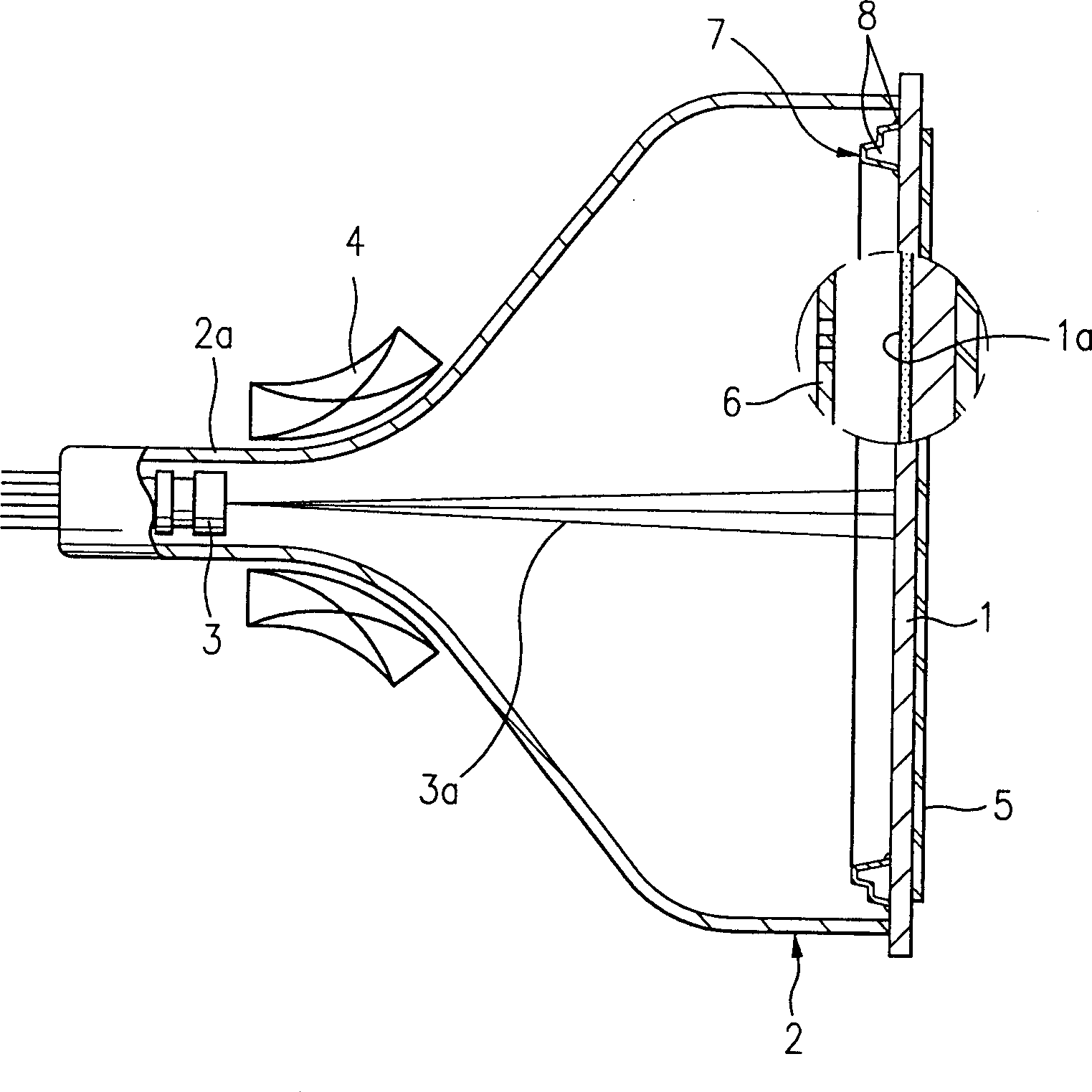
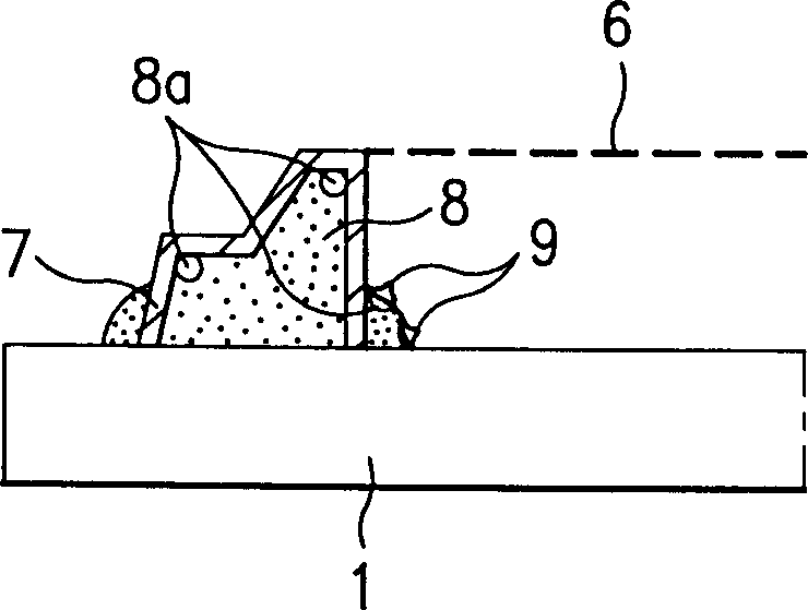
[0017] Fourth, if figure 2 As shown, during the application of the fluorescent material 1a, these fluorescent materials will penetrate into the many holes 8a of the fusing glass 8, and, in addition, during vacuuming, are inserted between the fusing glass 8 and the rail assembly 7 and between the fusing glass 8 and the guide rail assembly 7. Foreign matter between the panels 1 can block the perforations in the shadow mask 6
And, once the shadow mask 6 is welded to close the space between the shadow mask 6 and the guide rail assembly 7, foreign substances can no longer be removed, resulting in defective products.
[0018] Fifth, the residual gas that appears in the pores of the fusing glass 8 generated during welding is injected into the cathode ray tube under high vacuum, contaminating and destroying the quality of the cathode ray tube

Method used


Image

  • Panel-guide assembly in plain CRT
  • Panel-guide assembly in plain CRT
  • Panel-guide assembly in plain CRT

Examples


Embodiment Construction

[0034] Reference will now be made in detail to the preferred embodiments of the present invention, examples of which are illustrated in the accompanying drawings.

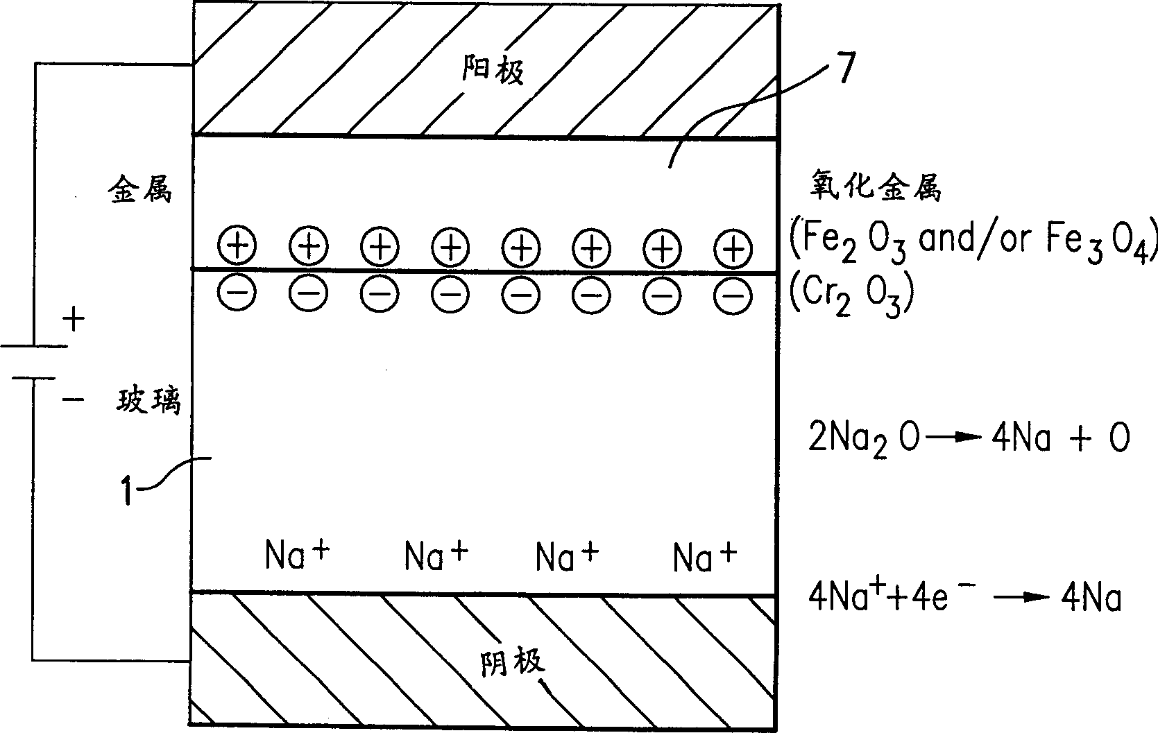
[0035] refer to Figure 3-5 , by coating the reaction catalyst aluminum AL or bismuth Bi on the guide rail assembly 1 to be bonded with the panel 1, and electrostatically bonding the panel 1 and the guide rail 7, the panel guide rail assembly of the present invention is processed. After coating the reaction catalyst, in the process of electrostatically bonding the panel 1 and the guide rail 7, the panel and the guide rail are aligned, and the required pressure (1-20Kgf / cm 2 ) is applied to them, the heating is roughly 300-520°C, and they are bonded with a suitable voltage selected in the range of DC200-4000V, and cooled to complete the bonding process.

[0036] At the same time, if image 3 As shown, the basic principle of electrostatic bonding employed in the present invention is to bond glass (panel) to metal (...


PUM


Abstract

A panel-rail assembly of a flat cathode-ray tube that can shorten the processing time as well as it improves adhesion strength with chemi cal reaction between ions moved within the panel and reaction promoter by adhering the panel and rail binder with electrostatic joining system after coating the rail surface facing the panel with reaction promoter that improves surface illuminance and adhesion with the panel. After coating the rail surface facing the panel with aluminum or bismuth, for this purpose, a voltage is applied between these panel and rail, causing the panel to produce oxygen ion, which performs chemical reaction with aluminum or bismuth written above while moving toward the rail to form Al2O3 or Bi2O3 on the joint face and together to reinforce the electrical bonding force, featuring this invention.

Description

technical field [0001] The present invention relates to a panel-rail assembly in a flat cathode ray tube, in particular the invention relates to a panel-rail assembly in a flat cathode ray tube in which a layer of Following the coating of the reaction catalyst, the panels and rails are electrostatically bonded, enhancing the bond and shortening the time period in which such bonding is required. Background technique [0002] Recently, a cathode ray tube, a device that actually displays an image on a display, has been developed as a flat cathode ray tube that eliminates image distortion and realizes a maximized viewing area in response to user demands. [0003] refer to figure 1 , the prior art flat cathode ray tube is equipped with a face plate 1 coated with a coating of a fluorescent material 1a on its inner surface, and a face plate 1 welded to the face plate having a cone 2 and a neck portion 2a. Zhou's external structure. In the flat cathode ray tube, there are electro...

Claims


Application Information

Patent Timeline
IPC IPC(8): H01J9/26G09G5/06H01J29/02H01J29/07
CPCH01J9/24H01J29/073H01J2229/0716
Inventor 千铉太
Owner LG ELECTRONICS INC
Learn More