
Metal building material bending equipment

A technology of building materials and equipment, which is applied in the field of bending equipment for metal building materials, can solve the problems of inconvenient cutting and achieve the effect of easy cutting

Active Publication Date: 2021-08-31
河北腾耀电子设备有限公司
View PDF7 Cites 3 Cited by
  • Summary
  • Abstract
  • Description
  • Claims
  • Application Information

AI Technical Summary

Problems solved by technology

[0005] In order to overcome the disadvantages of the prior art that people are required to perform bending manually and it is inconvenient to cut during the bending process, the technical problem to be solved is to provide a metal building material bending machine that can realize automatic bending and is convenient for automatic cutting. bending equipment

Method used


Image

  • Metal building material bending equipment
  • Metal building material bending equipment
  • Metal building material bending equipment

Examples


Embodiment 1

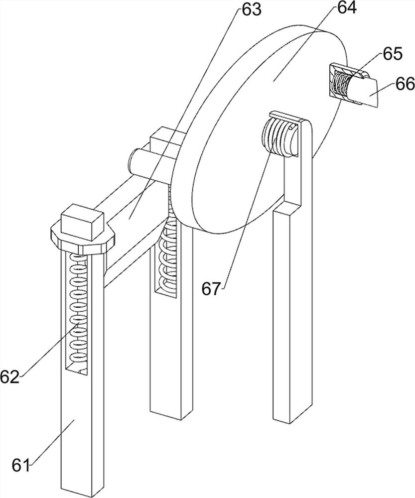
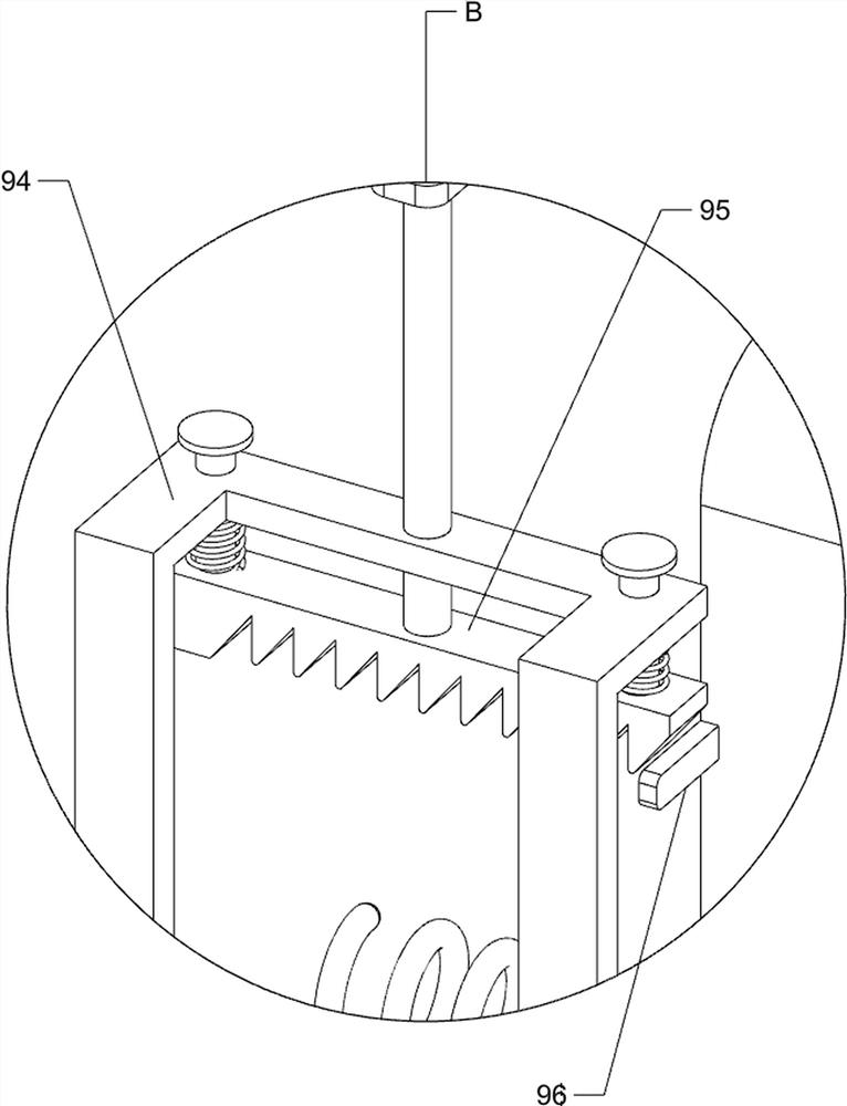
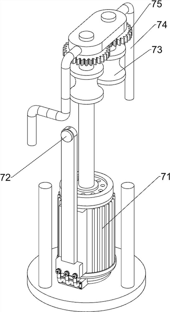
[0029] A metal building material bending equipment, such as figure 1 , figure 2 , image 3 and Figure 4 As shown, it includes a support frame 1, a cylinder 3, a bending block 4, a first rotating wheel 5, a bending mechanism 2, a cutting mechanism 6 and a feeding mechanism 7, and a bending mechanism 2 is arranged in the middle of the top of the support frame 1 to support A cylinder 3 is provided in the middle of the rear side of the frame 1, and a bending block 4 is provided on the front side of the piston rod of the cylinder 3. The bending block 4 is slidingly matched with the support frame 1, and two first rotating wheels are arranged symmetrically on the left and right sides of the support frame 1. 5. The upper right side of the support frame 1 is provided with a cutting mechanism 6, and the upper right side of the support frame 1 is provided with a feeding mechanism 7.

[0030] The bending mechanism 2 includes a first wedge block 21, a placement plate 22, a first chute...

Embodiment 2

[0035] On the basis of Example 1, such as Figure 5 , Figure 6 , Figure 7 , Figure 8 and Figure 9 As shown, it also includes a material taking assembly 8, and the material taking assembly 8 includes a third chute 81, a fourth spring 82, a third wedge block 83, a clamping block 84, a second torsion spring 85 and a rotating shaft 86, and the support frame 1 There are three third chute 81 on the top, and a third wedge-shaped block 83 is slid between the third chute 81, and a fourth spring 82 is respectively arranged between the third wedge-shaped block 83 and the third chute 81. Three wedge-shaped blocks 83 cooperate with the sliding type of first rotating wheel 5, and the left and right sides of the 3rd wedge-shaped block 83 front sides are all rotationally symmetrically provided with rotating shaft 86, and all rotationally on rotating shaft 86 are provided with clamping block 84, and clamping block 84 A second torsion spring 85 is provided between the third wedge block ...


PUM


Abstract

The invention relates to bending equipment, in particular to metal building material bending equipment. The technical problem to be solved is to provide the metal building material bending equipment, which can realize automatic bending and is convenient for automatic cutting. According to the technical scheme, the metal building material bending equipment comprises a supporting frame and a bending mechanism, and the bending mechanism is arranged in the middle of the top of the supporting frame; an air cylinder arranged in the middle of one side of the supporting frame; a bending block arranged on one side of a piston rod of the air cylinder, and the bending block is in sliding fit with the supporting frame; two first rotating wheels symmetrically arranged at the upper part of the supporting frame; a cutting mechanism arranged on one side of the upper portion of the supporting frame; and a feeding mechanism arranged on one side of the supporting frame. The metal building material bending equipment provided by the invention achieves the effects that automatic bending can be achieved, and automatic cutting is facilitated.

Description

technical field [0001] The invention relates to a bending device, in particular to a metal building material bending device. Background technique [0002] Bending is the elastic deformation of metal building materials under the pressure of the bending machine, and then plastic deformation. At the beginning, the metal building materials are naturally bent. With the pressure of the bending machine on the metal building materials, the metal building materials The ends are gradually approached, and after the pressure is applied, the metal building material will show a V-shaped bend. [0003] However, the existing technology requires people to manually press and bend, and excessive force during the bending process will make the curvature of the metal building material inconsistent, and it is impossible to cut during the bending process, and it needs to be cut after bending, which leads to time-consuming and labor-intensive people. , making people's labor intensity increase. [...

Claims


Application Information

Patent Timeline
Patent Type & Authority Applications(China)
IPC IPC(8): B21D7/06B21D43/28
CPCB21D7/06B21D43/28
Inventor 谢启林
Owner 河北腾耀电子设备有限公司
Learn More