
Electrical mounting rail bending machine

A technology of electrical installation and bending machine, which is applied in the field of electrical installation rails, can solve the problems of not having openings for electrical installation rails, and achieve the effects of saving manpower and improving work efficiency

Inactive Publication Date: 2020-02-07
ANHUI TECHN COLLEGE OF MECHANICAL & ELECTRICAL ENG
View PDF10 Cites 1 Cited by
  • Summary
  • Abstract
  • Description
  • Claims
  • Application Information

AI Technical Summary

Problems solved by technology

[0004] Chinese invention CN201610657752.4 discloses a metal strip bending machine. This metal strip bending machine can realize automatic bending of metal strips and improve the production efficiency of metal bending products, but it does not have the ability to open the electrical installation rail. The function of the hole, so a special production equipment is required for the production and processing of the electrical installation rail, which can also realize the opening of the hole while bending it

Method used


Image

  • Electrical mounting rail bending machine
  • Electrical mounting rail bending machine
  • Electrical mounting rail bending machine

Examples


Embodiment Construction

[0057] The technical solutions of the present invention will be further described below in conjunction with the accompanying drawings and through specific implementation methods.

[0058] Wherein, the accompanying drawings are only for illustrative purposes, showing only schematic diagrams, rather than physical drawings, and should not be construed as limitations on this patent; in order to better illustrate the embodiments of the present invention, some parts of the accompanying drawings will be omitted, Enlargement or reduction does not represent the size of the actual product; for those skilled in the art, it is understandable that certain known structures and their descriptions in the drawings may be omitted.

[0059] In the drawings of the embodiments of the present invention, the same or similar symbols correspond to the same or similar components; , "inner", "outer" and other indicated orientations or positional relationships are based on the orientations or positional ...


PUM


Abstract

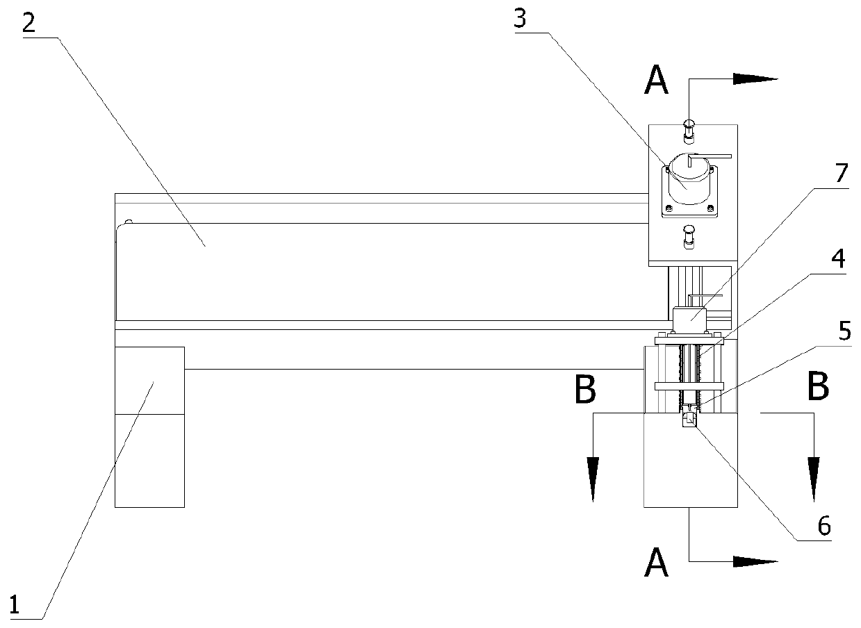
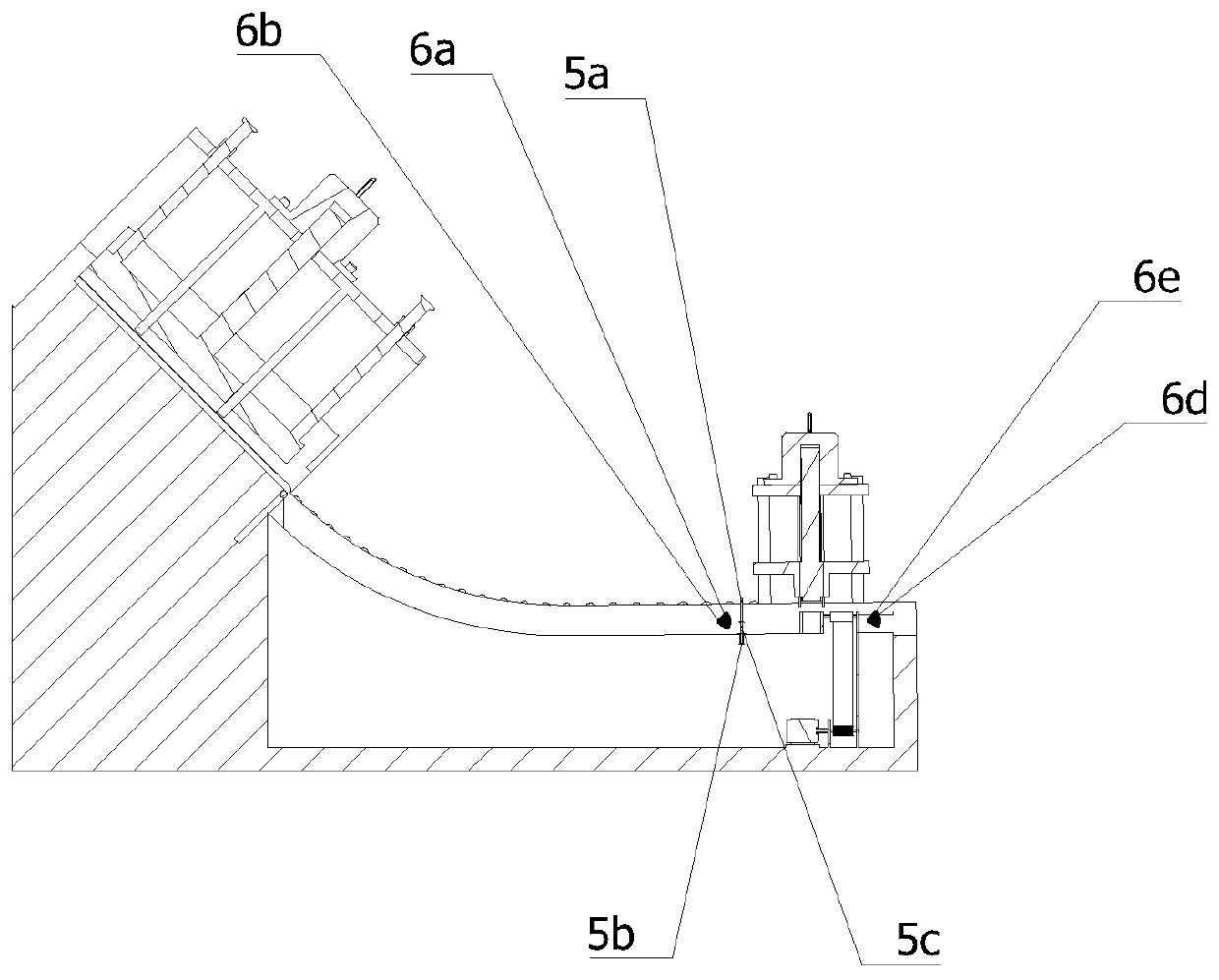
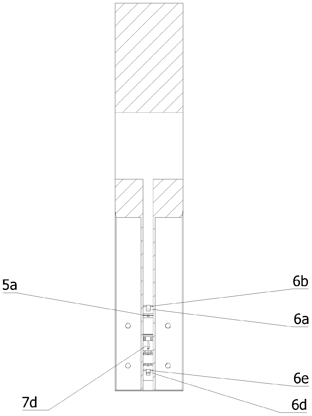
The invention relates to the field of electrical mounting rails, in particular to an electrical mounting rail bending machine. The electrical mounting rail bending machine comprises a rack, a linear transmission mechanism, a first stamping device, a slide rail mechanism, a material blocking mechanism, a step type feeding mechanism, a second stamping device, a sensor and a controller, wherein the linear transmission mechanism and the first stamping device are fixedly mounted on the rack in an inclined mode; the slide rail mechanism is arranged below the first stamping device; the material blocking mechanism is arranged on the slide rail mechanism; the sensor clings to the side, close to the first stamping device, of the material blocking mechanism; the step type feeding mechanism is mountedon the slide rail mechanism; the second stamping device is arranged above the slide rail mechanism; and the linear transmission mechanism, the first stamping device, the material blocking mechanism,the step type feeding mechanism, the second stamping device and the sensor are electrically connected to the controller. The electrical mounting rail bending machine realizes automatic bending and hole-forming of the electrical mounting rail, realizes automatic burr removal of the electrical mounting rail, saves labor power, improves working efficiency, is simple in structure, is easy to implementand is convenient to control.

Description

technical field [0001] The invention relates to the field of electric installation rails, in particular to an electric installation rail bending machine. Background technique [0002] The electrical installation rail is a kind of steel rail, which is generally made of galvanized steel (to prevent rust), and it is rarely made of aluminum alloy. It is mainly used to clamp electrical components on it, such as terminal blocks, relays, and switching power supplies. Wait. The structure of the electrical installation rail is relatively simple, but the amount used is very large. Generally, it is formed by stamping or bending, and then chamfered and deburred. Open the lower oval long hole to facilitate installation, and the shape of the electrical installation rail is inverted "several" or "G". [0003] During the production and manufacturing, it is necessary to bend and open holes for the electrical installation rails. At present, there are relatively few equipments on the market ...

Claims


Application Information

Patent Timeline
IPC IPC(8): B21D35/00B21D28/02B21D28/26B21D45/04B21D5/06B21D43/13B21D43/16B21D43/26B21D43/12B21C51/00
CPCB21C51/00B21D5/06B21D28/02B21D28/26B21D35/001B21D35/002B21D43/026B21D43/12B21D43/13B21D43/16B21D43/26B21D45/04
Inventor 李庆吴亚兰胡如方陈露王志伟朱稚华
Owner ANHUI TECHN COLLEGE OF MECHANICAL & ELECTRICAL ENG
Learn More