
Bending machine

A technology of a bending machine and a bending mechanism, applied in the field of bending, can solve the problems of high technical requirements of workers, waste of manpower, and unfavorable mass production.

Pending Publication Date: 2019-07-23
SUZHOU UNIV OF SCI & TECH
View PDF0 Cites 1 Cited by
  • Summary
  • Abstract
  • Description
  • Claims
  • Application Information

AI Technical Summary

Problems solved by technology

The above-mentioned operation method has high technical requirements for workers, wastes manpower, and has high production costs, which is not conducive to mass production.

Method used


Image

  • Bending machine
  • Bending machine
  • Bending machine

Examples


Embodiment Construction

[0016] Embodiments of the present invention are described in detail below, examples of which are shown in the drawings, wherein the same or similar reference numerals designate the same or similar elements or elements having the same or similar functions throughout. The embodiments described below by referring to the figures are exemplary and are intended to explain the present invention and should not be construed as limiting the present invention.

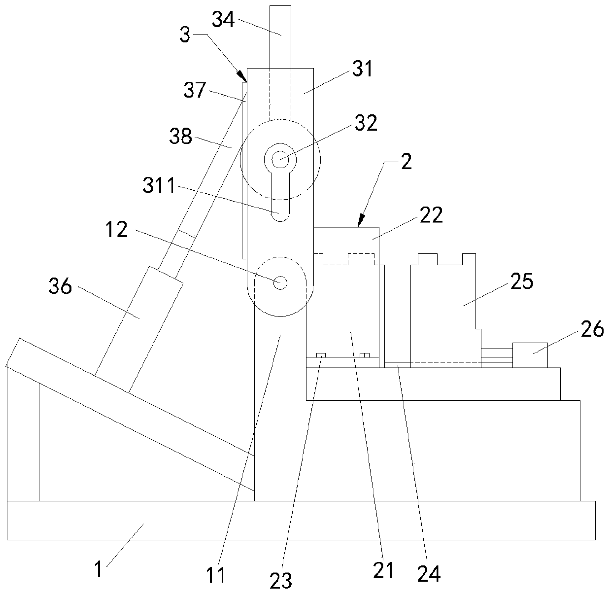
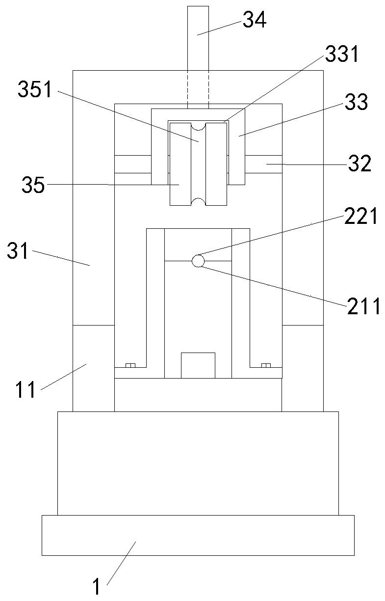
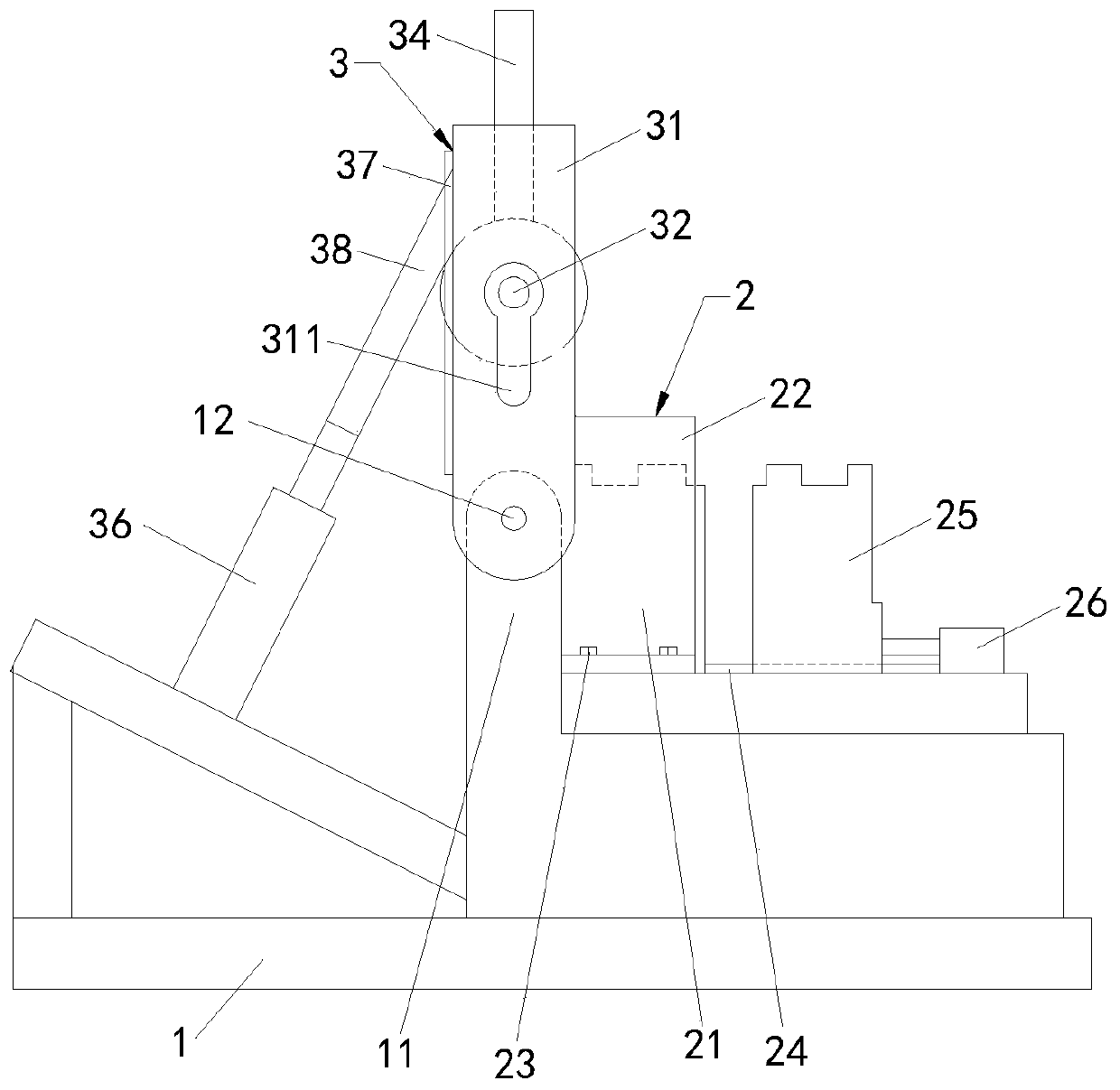
[0017] Such as figure 1 and figure 2 As shown, the present invention provides a bending machine, including a base 1, a positioning mechanism 2 arranged on the base 1, and a bending mechanism 3 arranged on one side of the positioning mechanism 2, and the bending mechanism 3 includes The rotating bracket 31, the bending shaft 32 installed on the rotating bracket 31, the fixed block 33 fixedly connected with the bending shaft 32, the guide provided on the top of the fixed block 33 and slidingly fitted with the rotating bracket 31 ...


PUM


Abstract

The invention provides a bending machine which comprises a base, a positioning mechanism on the base and a bending mechanism on one side of the positioning mechanism, wherein the bending mechanism comprises a rotary bracket, a bending shaft mounted on the rotary bracket, a fixed block fixedly connected with the bending shaft, a guiding shaft arranged at the top of the fixed block and in sliding fit with the rotary bracket, a bending block connected with the bending shaft, and a bending air cylinder for driving the rotary bracket to rotate. The positioning mechanism positions a product, and theproduct can be a pipe fitting or a sensor and the like with a smaller size; the bending mechanism bends one end of the product; in specific, after elevating the fixed block, the product is put into,the fixed block is pushed to descend, the bending air cylinder drives the rotary bracket to rotate, the rotary bracket drives the fixed block and the bending block to rotate by certain angle, and thebending block bends the product by certain angle, so that automatic bending of the product is realized, the bending curvature is fixed, the product quality is stable, manpower is saved and volume production is facilitated.

Description

technical field [0001] The invention relates to the technical field of bending, in particular to a bending machine. Background technique [0002] In the production process of some small-sized tubular products, such as curved sensors, it is necessary to partially bend the product. By manual bending, the bending degree varies, which affects product quality. In the prior art, there is a kind of bending machine that needs to manually put in the product and manually adjust the distance between the two bearing blocks. After the adjustment is completed, manually lock a gland and the bearing block through bolts, and press one end of the product Hold and fix, and then partially bend the product through the handle. The above-mentioned work operation mode has higher technical requirements for workers, wastes manpower, and has higher production costs, which is not conducive to mass production. Contents of the invention [0003] The technical problem solved by the present invention i...

Claims


Application Information

Patent Timeline
Patent Type & Authority Applications(China)
IPC IPC(8): B21D7/06B21D43/00
CPCB21D7/06B21D43/003
Inventor 刘义生吴永芝曹自洋牛福州牛雪梅苗静沈晔湖谢鸥殷振蒋全胜
Owner SUZHOU UNIV OF SCI & TECH
Learn More