Rapid roll changing mechanism

A roll changing mechanism and fast technology, applied in the direction of rolls, metal rolling stands, metal rolling mill stands, etc., can solve the problems of affecting the efficiency of roll changing, long time consumption, long time consumption of universal joint couplings, etc.

Active Publication Date: 2021-08-31
广东肇庆西江机械制造有限公司
View PDF8 Cites 1 Cited by
  • Summary
  • Abstract
  • Description
  • Claims
  • Application Information

AI Technical Summary

Problems solved by technology

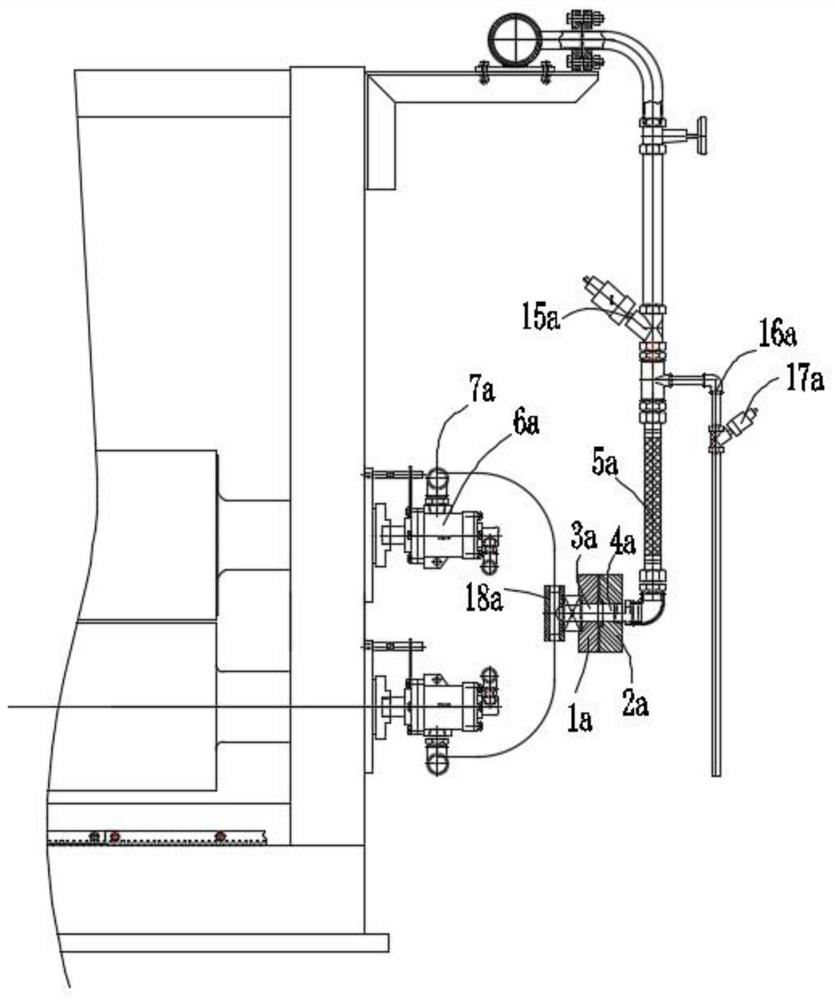
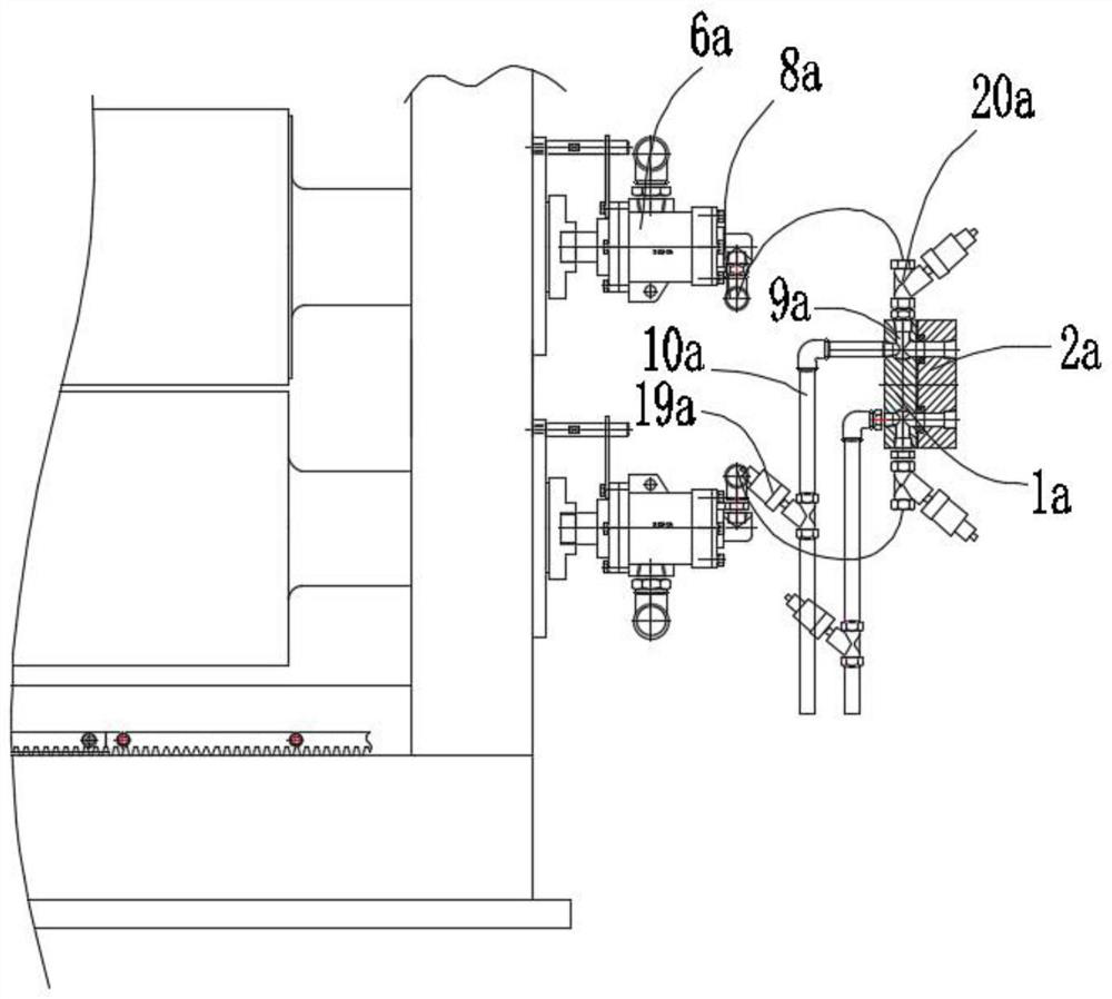
[0002] The existing toothed roller transmission mechanism includes a motor and a reducer, the toothed roller is connected to the frame in rotation, the motor and the reducer are driven by a belt, and the toothed roller and the output shaft of the reducer are connected by a universal joint coupling. When it is necessary to change the toothed rollers, the universal joint coupling connecting the toothed rollers must be disassembled manually with the help of tools, and then the toothed rollers can be removed for the toothed roller replacement process. The efficiency is low. In addition, when the toothed roller needs to be replaced, the steam inlet metal hose and the drainage metal hose connected to the upper and lower toothed rollers must be disassembled before the roller can be replaced. The existing toothed roller and the steam inlet metal hose and the drainage The metal hoses are connected by pipe joints. When disassembling the metal hoses for steam intake, exhaust, and drainage, manual tools are required to remove the connection. The temperature of the outer wall is relatively high. When disassembling the metal hoses for steam inlet and exhaust, it is necessary to wait until the steam in the metal hoses for inlet and exhaust steam has been exhausted and cooled down before disassembling. Otherwise, it is easy to accidentally touch the metal hoses during manual operation. Burning, long time-consuming, affect the efficiency of changing rolls, in order to improve the above shortcomings, it is necessary to make improvements to the existing technology

Method used


Image

  • Rapid roll changing mechanism
  • Rapid roll changing mechanism
  • Rapid roll changing mechanism

Examples


Embodiment Construction

[0034] In order to more clearly illustrate the embodiments of the present invention or the technical solutions in the prior art, the present invention will be further introduced below in conjunction with specific embodiments and accompanying drawings. Obviously, the accompanying drawings in the following description are only some embodiments of the present invention , for those skilled in the art, other drawings can also be obtained according to these drawings on the premise of not paying creative work.

[0035] It should be understood that the orientation or positional relationship indicated by the terms "upper", "lower", "front", "rear", "left", "right", "horizontal", "top", "inner" etc. are based on The orientation or positional relationship shown in the drawings is only for the convenience of describing the present invention and simplifying the description, and does not indicate or imply that the referred device or element must have a specific orientation, be constructed an...


PUM


Abstract

The invention relates to a rapid roller changing mechanism. The rapid roller changing mechanism comprises a rack, the rack is provided with a power mechanism and a steam locking mechanism, the power mechanism comprises a tensioning assembly, the tensioning assembly can drive a tensioning pulley to move so that the tensioning pulley can pull a transmission synchronous belt, so that the transmission synchronous belt is in meshed connection with a tooth roller pulley, a transmission shaft of a transmission motor rotates, trough transmission of a transition synchronous belt, the transmission synchronous belt drives the tooth roller pulley to rotate, namely, an upper tooth roller and a lower tooth roller can be driven to rotate, when the tooth rollers need to be replaced, the tensioning assembly drives the tensioning pulley to reset, the transmission synchronous belt is loosened, the tooth rollers can be moved away for the tooth roller replacing procedure when the transmission synchronous belt is not in meshed connection with the tooth roller pulley, consumed time is short, the roller replacing efficiency is high, after steam in a drainage metal hose is completely discharged, an upper valve body and a lower valve body can be separated, the defects that the rollers can be rapidly replaced without detaching steam inlet and drainage metal hoses, and scalding is prone to occurring are overcome, a conveying trolley is arranged below the rack, the tooth rollers are conveyed through the conveying trolley, and the roller replacing efficiency is improved.

Description

technical field [0001] The invention relates to the technical field of shaft changing equipment, in particular to a quick roller changing mechanism. Background technique [0002] The existing toothed roller transmission mechanism includes a motor and a reducer, the toothed roller is connected to the frame in rotation, the motor and the reducer are driven by a belt, and the toothed roller and the output shaft of the reducer are connected by a universal joint coupling. When it is necessary to change the toothed rollers, the universal joint coupling connecting the toothed rollers must be disassembled manually with the help of tools, and then the toothed rollers can be removed for the toothed roller replacement process. The efficiency is low. In addition, when the toothed roller needs to be replaced, the steam inlet metal hose and the drainage metal hose connected to the upper and lower toothed rollers must be disassembled before the roller can be replaced. The existing toothed ...

Claims


Application Information

Patent Timeline
Patent Type & Authority Applications(China)
IPC IPC(8): B21B31/08B21B35/00B21B27/08
CPCB21B31/08B21B35/00B21B27/08B21B2027/086
Inventor 陈敬谦谢钰成杨小东杨泽宇陈振华孔祥勇邱达泉黎伟健陆航
Owner 广东肇庆西江机械制造有限公司
Why Eureka
Try Eureka