
Constant temperature distribution box

A distribution box and constant temperature technology, which is applied in the field of power transmission and distribution, can solve the problems of affecting the working state of electrical appliances and the unstable operation of electrical appliances in the distribution box, and achieve the effect of improving stability.

Inactive Publication Date: 2021-08-27
郑蓓
View PDF0 Cites 0 Cited by
  • Summary
  • Abstract
  • Description
  • Claims
  • Application Information

AI Technical Summary

Problems solved by technology

[0003] In the prior art, a fan is usually installed in the distribution box to cool down the electrical appliances in the box to maintain a stable and reasonable working temperature in the hot season. Influenced by the coming temperature, when the climate is cold in winter, the temperature in the box is too low will also affect the working state of the electrical appliances, resulting in unstable operation of the electrical appliances in the distribution box

Method used


Image

  • Constant temperature distribution box
  • Constant temperature distribution box
  • Constant temperature distribution box

Examples


Embodiment approach

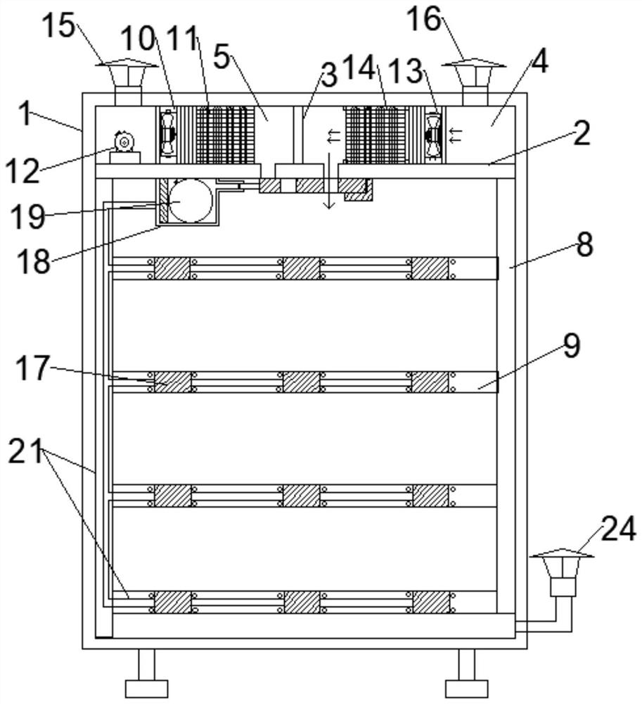
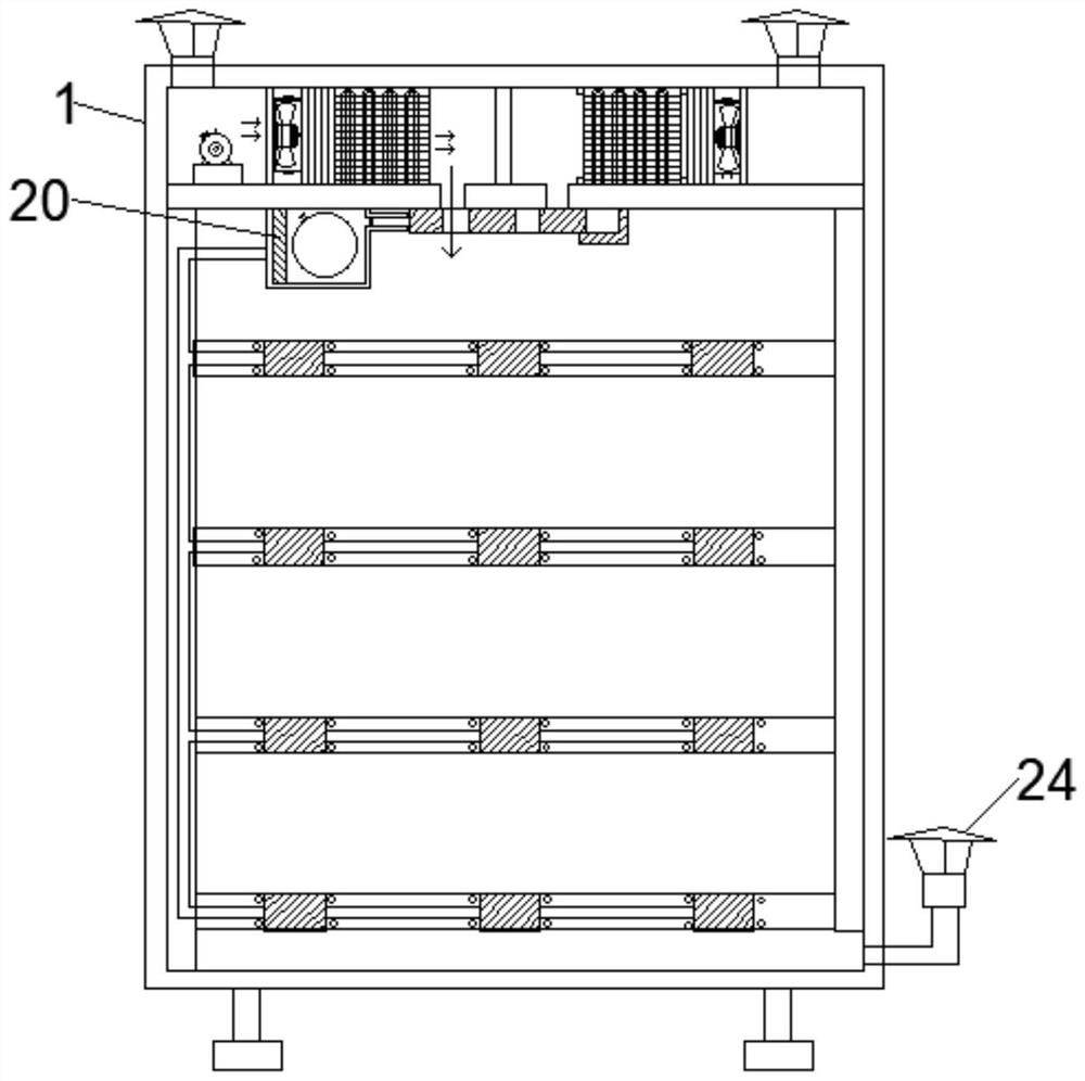
[0039] As an optional implementation, the air conditioner includes:

[0040] The radiator is arranged in the hot air chamber 5 and includes a heat dissipation fan 10, a heat dissipation grid 11 and a first U-shaped pipe winding inside the heat dissipation grid 11. The upper end of the heat dissipation grid 11 is connected to the top of the box body 1, and the lower end is connected to the transverse partition. plate 2, the heat dissipation grill 11 is arranged between the heat dissipation fan 10 and the hot air outlet 7, and the heat dissipation fan 10 blows the hot air from the heat dissipation grill 11 to the heat dissipation outlet;

[0041] The compressor 12 is arranged in the hot air chamber 5 and communicates with the first U-shaped pipe through the first pipe;

[0042] The refrigerator is arranged in the cold air chamber 4 and includes a cold fan 13, a cold air grid 14 and a second U-shaped pipe winding inside the cold air grid 14. The upper end of the cold air grid 14 ...


PUM


Abstract

One or more embodiments of the present specification provide a constant temperature distribution box comprising: a box body; a transverse partition plate which is arranged on the upper portion in the box body and divides the space in the box body into an upper temperature adjusting chamber and a lower electric appliance installation chamber, wherein an air conditioning device is arranged in the temperature adjusting chamber, the temperature adjusting chamber further comprises a longitudinal partition plate which divides the temperature adjusting chamber into a cold air chamber and a hot air chamber, a cold air opening and a hot air opening are formed in the transverse partition plate, the cold air port communicates with the cold air chamber and the electric appliance installation chamber, and the hot air port communicates with the hot air chamber and the electric appliance installation chamber. According to the constant temperature distribution box provided by the invention, the cold air chamber and the hot air chamber are arranged in the box body, the cold air chamber blows cold air into the electrical installation chamber when the temperature of the electrical appliance in the box body is relatively high so as to cool the electrical appliance, and the hot air chamber blows hot air into the electrical installation chamber when the temperature of the electrical appliance in the box body is relatively low so as to cool the electrical appliance. In conclusion, the working temperature of the electric appliance can be maintained at a reasonable level, and the working stability of the electric appliance is effectively improved.

Description

technical field [0001] One or more embodiments of this specification relate to the technical field of power transmission and distribution, and in particular to a constant temperature distribution box. Background technique [0002] As an edge component of the power system, the distribution box plays an important role. It distributes the electric energy from the transmission grid in the next step, which directly affects the user's power consumption experience. The existing distribution box is usually installed outdoors, not only To experience the wind and rain, more importantly, the internal electrical appliances must withstand the temperature changes brought about by the seasons. [0003] In the prior art, a fan is usually installed in the distribution box to cool down the electrical appliances in the box to maintain a stable and reasonable working temperature in the hot season. Influenced by the coming temperature, when the climate is cold in winter, the temperature in the ...

Claims


Application Information

Patent Timeline
Patent Type & Authority Applications(China)
IPC IPC(8): H02B1/56H02B1/28H02B1/04
CPCH02B1/04H02B1/28H02B1/56
Inventor 郑蓓
Owner 郑蓓
Learn More