
Automatic purging and replacing system and method for hydrogen-related pipe valve testing gas circuit structure

A technology of pipe valve and gas circuit, which is applied in the field of automatic purge replacement system for hydrogen-related pipe valve parts test gas circuit structure, can solve the problem that the hydrogen energy pipe valve part test system lacks effective and reliable removal of residual hydrogen and impurities, etc. Achieve the effects of simple structure, low maintenance cost and improved accuracy

Active Publication Date: 2021-08-27
正星氢电科技郑州有限公司
View PDF6 Cites 2 Cited by
  • Summary
  • Abstract
  • Description
  • Claims
  • Application Information

AI Technical Summary

Problems solved by technology

[0005] The purpose of the present invention is to provide an automatic purging and replacement system and method for testing the gas circuit structure of hydrogen-related tube valve parts, so as to solve the problem that the hydrogen tube valve part testing system lacks effective and reliable technology for removing residual hydrogen and impurities

Method used


Image

  • Automatic purging and replacing system and method for hydrogen-related pipe valve testing gas circuit structure
  • Automatic purging and replacing system and method for hydrogen-related pipe valve testing gas circuit structure
  • Automatic purging and replacing system and method for hydrogen-related pipe valve testing gas circuit structure

Examples


Embodiment Construction

[0026] The specific implementation of the present invention will be described below in conjunction with the accompanying drawings and examples, but the following examples are only used to describe the present invention in detail, and do not limit the scope of the present invention in any way.

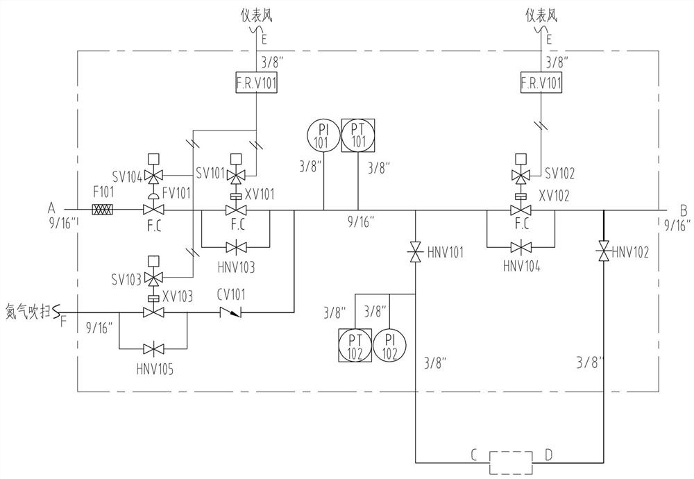
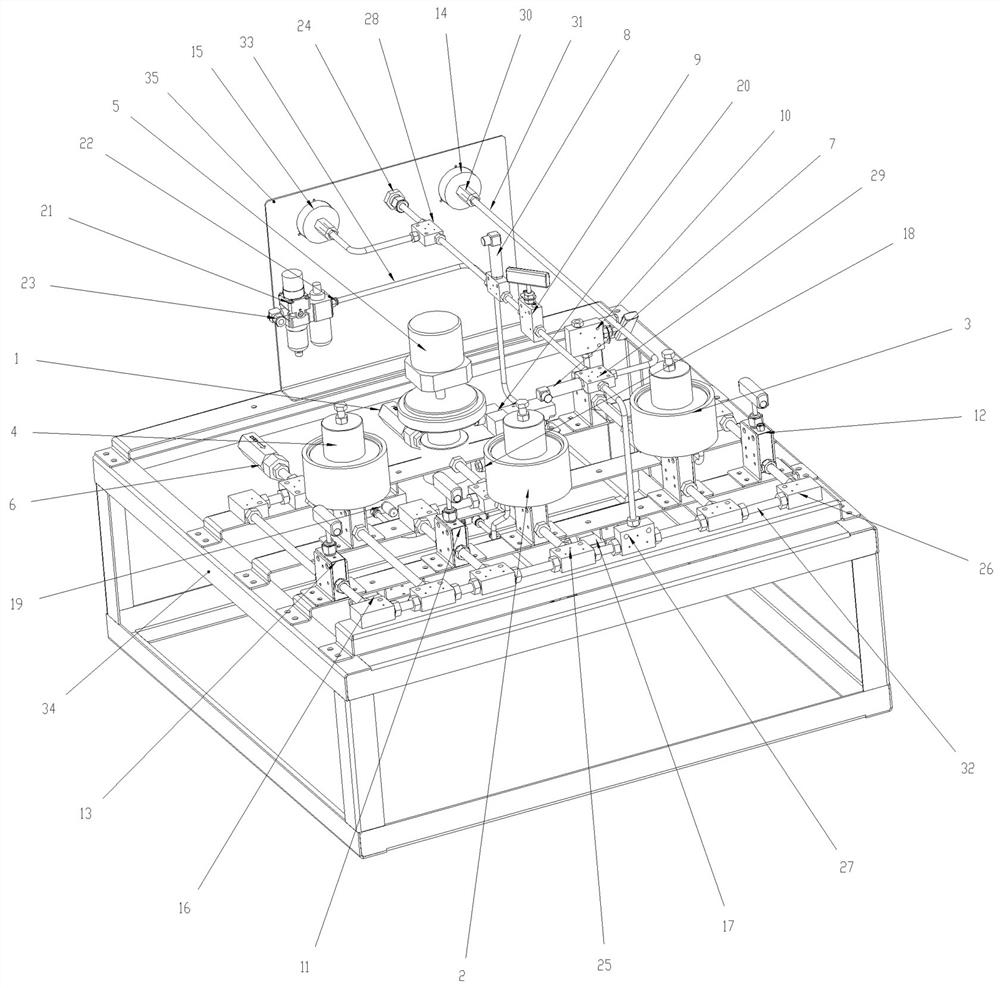
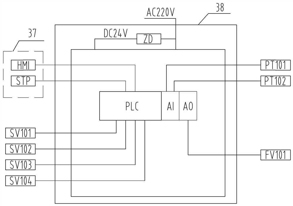
[0027] Example: Automatic purge replacement system for hydrogen-related pipe valve parts test gas path structure, see Figure 1 to Figure 5 ,mainly includes:

[0028] It includes a purge gas source, a PLC control unit, and a purge replacement pipeline for sending purge gas into the corresponding main pipeline and test pipeline, and the purge replacement pipeline includes purge inlets connected in sequence by corresponding pipelines F, purge pneumatic valve (XV103) 4, check valve (CV101) 6, the purge inlet F is connected to the corresponding purge gas source (compressed nitrogen); the purge pneumatic valve (XV103) 4 is connected in parallel Corresponding bypass branches, and each bypass...


PUM


Abstract

The invention discloses an automatic purging and replacing system and method for a hydrogen-related pipe valve testing gas circuit structure. The system comprises a purging gas source, a purging and replacing pipeline used for feeding purging gas into a main pipeline and a testing pipeline, and a PLC control unit; the purging and replacing pipeline comprises a purging inlet, a pneumatic valve and a one-way valve, which are sequentially connected through corresponding pipelines; the purging inlet is connected with the corresponding purging gas source; before testing or debugging of a pipe valve, all stop valves in a tested pipeline structure are opened, and corresponding centralized diffusion pipelines are communicated; after the purging inlet communicates with the purging gas source, the pneumatic valve is opened to release purging gasflow for pipeline purging; and after purging is completed, all the stop valves are closed, the pipe valve to be tested is connected with a mounting piece to be arranged in the corresponding tested pipeline, and subsequent testing or debugging is carried out. The system is simple in structure, practical and low in use cost; and according to the method, residual hydrogen, impurities and waste in the tested pipeline can be effectively purged and cleaned in time, potential safety hazards are eliminated, and the accuracy and reliability of a test result are improved.

Description

technical field [0001] The invention relates to the technical field of detection of new energy pipe valve parts, in particular to an automatic purging and replacement system and method for testing gas circuit structures of hydrogen-related pipe valve parts. Background technique [0002] With the continuous growth of the human population base and the rapid improvement of living standards, the consumption of non-renewable resources such as fossil fuels, coal, and natural gas is increasing day by day, which has led to increasing pollution of the natural environment. Currently, exploring and developing sustainable and clean energy technologies has become a top priority. Hydrogen energy is an extremely rich, inexhaustible and inexhaustible new energy that can be developed today; hydrogen is an ideal clean energy carrier, and it is also recognized by the world and has the most hope of becoming a new energy source in the 21st century. The clean new energy that human beings desire....

Claims


Application Information

Patent Timeline
Patent Type & Authority Applications(China)
IPC IPC(8): F17D1/065F17D3/01B08B5/02
CPCF17D1/065F17D3/01B08B5/02Y02P90/45
Inventor 周亮李明昕贾艳明黄景龙
Owner 正星氢电科技郑州有限公司
Learn More