
Patsnap Eureka
For R&D, Patsnap Eureka makes reading and utilizing patents & technical documents easy.
Patsnap Eureka AIR
Designed for self-driven R&D workflows. Generate viable solutions, solve complex R&D challenges, empower your innovation with AI.

Patsnap Eureka Materials
Designed for material experts only. Revolutionize your material R&D, from search, analyze, to developing new materials.

TechResearch
Generate reliable direction feasibility study reports for your R&D in just a few steps.

TechSeek
Discover and master advanced knowledge NOW. Basics, ideas, possibilities, all at once.

TechMind
As an expert in R&D Theories, TechMind can generates customized viable solutions instantly.

TechRisk
Analyze your overall solution with one click, know your potential R&D risks in advance.

TechMonitor
Get weekly tech updates, stay abreast of the latest tech innovations and key insights.
Hydraulic accumulator gas charging device and its gas charging method based on oilfield petrochemical
The technology of hydraulic accumulator and air charging device is applied in the direction of container filling method, container discharge method, pressure vessel, etc., which can solve the problems of narrow application range, unfavorable use, and air pressure reduction, and achieve wide application range, simple operation, good effect
- Summary
- Abstract
- Description
- Claims
- Application Information
AI Technical Summary
Problems solved by technology
Method used
Image

Examples
Embodiment 1
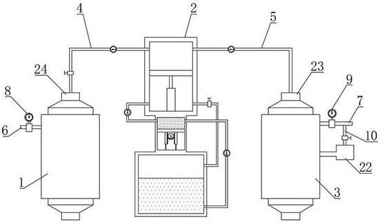
[0055] like Figure 1-6 As shown, the hydraulic accumulator charging device based on oil field petrochemical proposed by the present invention includes a nitrogen tank 1, an accumulator 3, a gas delivery pipe 4, an inflation pipe 5, a first connection assembly 23 and a second connection assembly 24, and the gas delivery pipe 4 is connected with the nitrogen tank 1 through the second connection assembly 24, the gas charging pipe 5 is connected with the accumulator 3 through the first connection assembly 23, the nitrogen tank 1 is equipped with a first air guide tube 6, and the first air guide tube 6 is equipped with a second An air pressure sensor 8, and the end of the first air guide tube 6 away from the nitrogen tank 1 is closed, the first air pressure sensor 8 detects the air pressure in the nitrogen tank 1, and the second air guide tube 7 is installed on the accumulator 3. A second air pressure sensor 9 is installed on the two air guide tubes 7, and the end of the second ai...
Embodiment 2
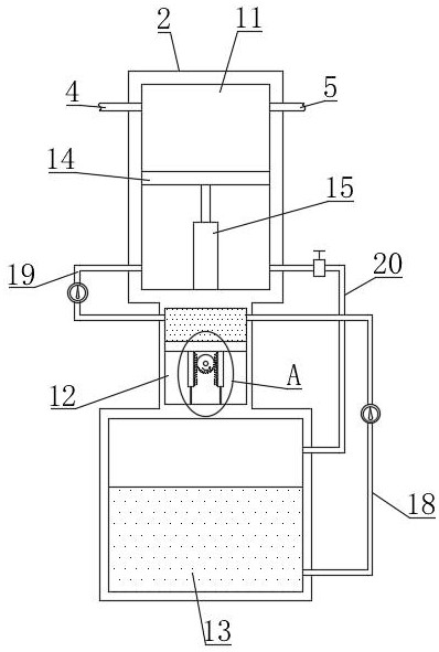
[0065] Such as Figure 7 As shown, the difference between this embodiment and Embodiment 1 is that a guide pull-down assembly 15 is installed on the bottom of the first piston plate 14, and the guide pull-down assembly 15 includes a first connecting cylinder 1501, a second connecting cylinder 1502, a stop ring 1503, The vertical bar 1504 and the first spring 1505, the first connecting cylinder 1501 is vertically arranged and fixedly installed on the bottom of the first piston plate 14 by bolts, the opening of the first connecting cylinder 1501 is downward, the second connecting cylinder 1502 is vertically arranged and Installed on the bottom of the pressurized chamber 11 by bolts, the opening of the second connecting cylinder 1502 faces upward, and the first connecting cylinder 1501 is inserted downward into the second connecting cylinder 1502, and the vertical rod 1504 is vertically arranged on the second connecting cylinder 1502 insert into the first connecting cylinder 1501...
Embodiment 3
[0068] Such as Figure 8 As shown, the difference between this embodiment and Embodiment 1 and Embodiment 2 is that a pressure relief pipe 10 is installed vertically at the end of the second air duct 7, and the end of the pressure relief pipe 10 away from the second air duct 7 is connected to the slow release box 22, and a pressure relief valve is installed on the pressure relief pipe 10. When the air pressure in the accumulator 3 is greater than a certain value, the pressure relief pipe 10 will discharge the gas inside the accumulator 3 to relieve pressure and prevent energy storage The internal air pressure of device 3 is too high to cause explosion, so as to avoid potential safety hazards; slow release box 22 includes box body 2201, grid plate 2202, fixed rod 2203 and the third spring 2204, and the top of box body 2201 communicates with pressure relief pipe 10 , the bottom of the box body 2201 is open, and the inner sides of the box body 2201 are equipped with fixed rods 22...
PUM
 Abstract
Description
Claims
Application Information
 - R&D Engineer
- R&D Manager
- IP Professional
- Industry Leading Data Capabilities
- Powerful AI technology
- Patent DNA Extraction
Browse by: Latest US Patents, China's latest patents, Technical Efficacy Thesaurus, Application Domain, Technology Topic, Popular Technical Reports.
© 2024 PatSnap. All rights reserved.Legal|Privacy policy|Modern Slavery Act Transparency Statement|Sitemap|About US| Contact US: help@patsnap.com