Hydraulic accumulator inflation device based on oilfield petrochemical engineering and inflation method thereof

A technology of hydraulic accumulators and inflatable devices, which is applied to container filling methods, container discharge methods, pressure vessels, etc., can solve problems such as narrow application range, unfavorable use, and air pressure reduction, and achieve wide application range and good use effect , the effect of easy operation

Active Publication Date: 2021-08-27
山东辛丁技术有限公司
View PDF20 Cites 3 Cited by
  • Summary
  • Abstract
  • Description
  • Claims
  • Application Information

AI Technical Summary

Problems solved by technology

[0003] After a period of use, the internal air pressure of the hydraulic accumulator decreases, which affects the energy supply of the accumulator, and it is necessary to replenish the gas in the accumulator from time to time. At present, the nitrogen cylinder is directly connected to the accumulator. In the air chamber, nitrogen gas is charged into the accumulator by relying on the pressure of the nitrogen tank, but this charging method can only meet the condition that the gas pressure in the accumulator is low. When the gas in the accumulator is required to reach the final When the pressure is high, that is, when the air pressure value in the nitrogen tank is lower than the final air pressure value in the accumulator, the accumulator cannot be inflated in this way, and the scope of application is narrow, which is not conducive to use, and the existing The inflatable device cannot select the optimal inflation mode and inflate automatically according to the actual situation, the operation is not easy enough, and it is not conducive to improving its scope of application, and the use effect needs to be improved;

Method used


Image

  • Hydraulic accumulator inflation device based on oilfield petrochemical engineering and inflation method thereof
  • Hydraulic accumulator inflation device based on oilfield petrochemical engineering and inflation method thereof
  • Hydraulic accumulator inflation device based on oilfield petrochemical engineering and inflation method thereof

Examples


Embodiment 1

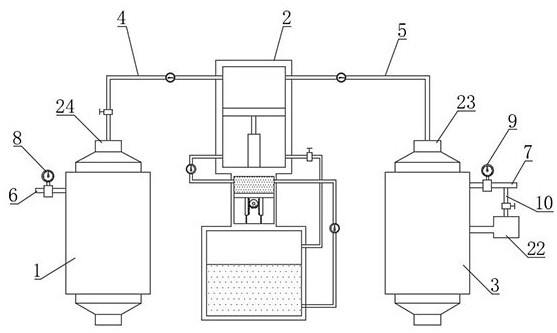
[0055] Such as Figure 1-6 As shown, the hydraulic accumulator charging device based on oil field petrochemical proposed by the present invention includes a nitrogen tank 1, an accumulator 3, a gas delivery pipe 4, an inflation pipe 5, a first connection assembly 23 and a second connection assembly 24, and the gas delivery pipe 4 is connected with the nitrogen tank 1 through the second connection assembly 24, the gas charging pipe 5 is connected with the accumulator 3 through the first connection assembly 23, the nitrogen tank 1 is equipped with a first air guide tube 6, and the first air guide tube 6 is equipped with a second An air pressure sensor 8, and the other end of the first air guide tube 6 is closed, the first air pressure sensor 8 detects the air pressure in the nitrogen tank 1, the second air guide tube 7 is installed on the accumulator 3, the second air guide tube 7 is equipped with a second air pressure sensor 9, and the other end of the second air guide tube 7 i...

Embodiment 2

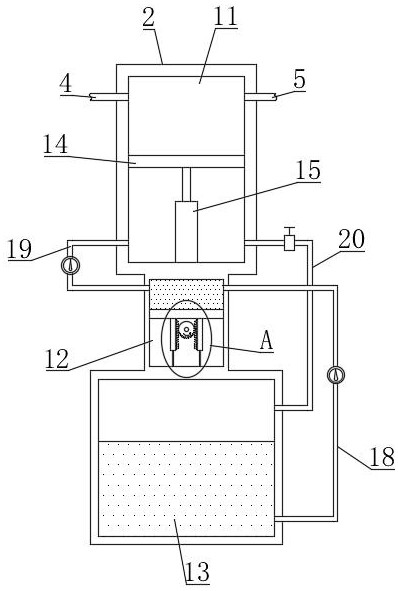
[0065] Such as Figure 7 As shown, the difference between this embodiment and Embodiment 1 is that a guide pull-down assembly 15 is installed on the bottom of the first piston plate 14, and the guide pull-down assembly 15 includes a first connecting cylinder 1501, a second connecting cylinder 1502, a stop ring 1503, The vertical bar 1504 and the first spring 1505, the first connecting cylinder 1501 is vertically arranged and fixedly installed on the bottom of the first piston plate 14 by bolts, the opening of the first connecting cylinder 1501 is downward, the second connecting cylinder 1502 is vertically arranged and Installed on the bottom of the pressurized chamber 11 by bolts, the opening of the second connecting cylinder 1502 faces upward, and the first connecting cylinder 1501 is inserted downward into the second connecting cylinder 1502, and the vertical rod 1504 is vertically arranged on the second connecting cylinder 1502 insert into the first connecting cylinder 1501...

Embodiment 3

[0068] Such as Figure 8 As shown, the difference between this embodiment and Embodiment 1 and Embodiment 2 is that a pressure relief pipe 10 is vertically installed at the end of the second air guide pipe 7, and the other end of the pressure relief pipe 10 is connected with a slow release box 22, and the pressure relief A pressure relief valve is installed on the pipe 10. When the air pressure in the accumulator 3 is greater than a certain value, the pressure relief pipe 10 will discharge the gas inside the accumulator 3 to relieve pressure and prevent the internal air pressure of the accumulator 3 from Excessively high and explode, avoid to bring potential safety hazard; Sustained release box 22 comprises box body 2201, grid plate 2202, fixed rod 2203 and the 3rd spring 2204, and the top of box body 2201 is communicated with pressure relief pipe 10, and the top of box body 2201 The bottom is open, and the inner sides of the box body 2201 are equipped with fixed rods 2203 thr...


PUM


Abstract

The invention relates to the technical field of fluid pressure actuators, mainly relates to an accumulator inflation device, in particular to a hydraulic accumulator inflation device based on oilfield petrochemical engineering and an inflation method thereof, and aims to solve the problems that nitrogen is inflated into an accumulator mainly depending on the pressure in a nitrogen tank at present, and when the final pressure of gas in the accumulator is required to be higher, the accumulator cannot be inflated in the mode, and the application range is narrow; and an existing inflation device cannot select the optimal inflation mode and automatically conduct inflation according to actual conditions. The inflation device comprises a nitrogen tank, wherein a gas pipe is connected with the nitrogen tank, a gas-filled tube is connected with an accumulator, and a pressurization box is arranged between the nitrogen tank and the accumulator. According to the device and the method, the optimal inflation mode can be obtained according to the actual conditions, inflation can be automatically conducted, the output nitrogen can be pressurized, inflation can be smoothly conducted when the requirement for the pressure of gas in the accumulator is high, and the application range is wide.

Description

technical field [0001] The invention relates to the technical field of fluid pressure actuators, and mainly relates to an accumulator inflation device, in particular to an oilfield petrochemical-based hydraulic accumulator inflation device and an inflation method thereof. Background technique [0002] The hydraulic accumulator is an energy conversion element that converts the pressure energy of the working medium into other energy forms such as potential energy and stores it. The hydraulic accumulator can release its stored energy for a short time and use it for the work of the system; in addition, The hydraulic accumulator can also absorb the vibration and shock generated by the system. The placement position in the hydraulic circuit varies with its function. When absorbing hydraulic shock or pressure pulsation, it should be installed near the shock source or pulsation source. Near the relevant actuators, hydraulic accumulators can be divided into gravity type, spring type ...

Claims


Application Information

Patent Timeline
Patent Type & Authority Applications(China)
IPC IPC(8): F15B1/08F15B1/22F17C7/00F17C5/06F17C13/02F17C13/04F17C13/00
CPCF15B1/08F15B1/22F17C5/06F17C7/00F17C13/00F17C13/02F17C13/025F17C13/04F17C2221/014F17C2227/01F17C2250/032F17C2250/034F17C2250/072
Inventor 林荣泞
Owner 山东辛丁技术有限公司
Why Eureka
Try Eureka