
Turntable head locking mechanism

A locking mechanism and head technology, applied in the direction of electromechanical devices, vehicle components, control mechanical energy, etc., can solve the problems of optical components, vibration and shaking of the turntable, etc., and achieve the effect of preventing damage and accurate viewing and aiming

Pending Publication Date: 2021-08-27
江苏北方湖光光电有限公司
View PDF0 Cites 0 Cited by
  • Summary
  • Abstract
  • Description
  • Claims
  • Application Information

AI Technical Summary

Problems solved by technology

[0004] After the U-shaped turntable is powered on, it reaches the zero position instantaneously under the action of the motor and the code disc. After the power is turned off, the azimuth mechanism and the pitch mechanism can move freely, so that the U-shaped turntable installed on the vehicle will be caused by the movement of the vehicle after the power is turned off. The vibration and shaking of the turntable will have a certain impact on the optical components in the head, so a locking mechanism that can lock and fix the U-shaped turntable after power failure is proposed to solve the above problems

Method used


Image

  • Turntable head locking mechanism
  • Turntable head locking mechanism
  • Turntable head locking mechanism

Examples


Embodiment 1

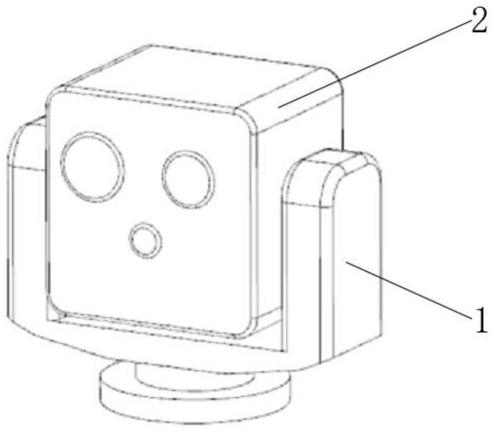
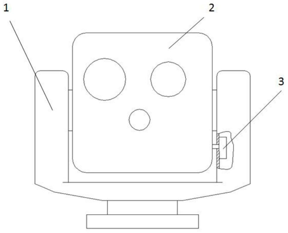
[0024] see Figure 1-5 , this embodiment provides a turntable head locking mechanism, including a U-shaped mounting frame 1, the bottom of the mounting frame 1 is fixed to the vehicle body, the mounting frame 1 can realize the isolation between the rotary head 2 and the vehicle body, and avoid The vibration directly affects the rotor 2, and can also carry the load on the rotor 2, which is convenient for the rotor 2 to detect the change of direction.

[0025] The interior of the mounting frame 1 is equipped with a rotor 2 through a rotating shaft. The rotor 2 is a prior art with a variety of light point devices integrated inside, which can be applied to the vehicle for detection and aiming at the target. It is equivalent to the driver's eyes, allowing the driver to The driver and operator can accurately observe the situation outside the vehicle while protecting the vehicle body.

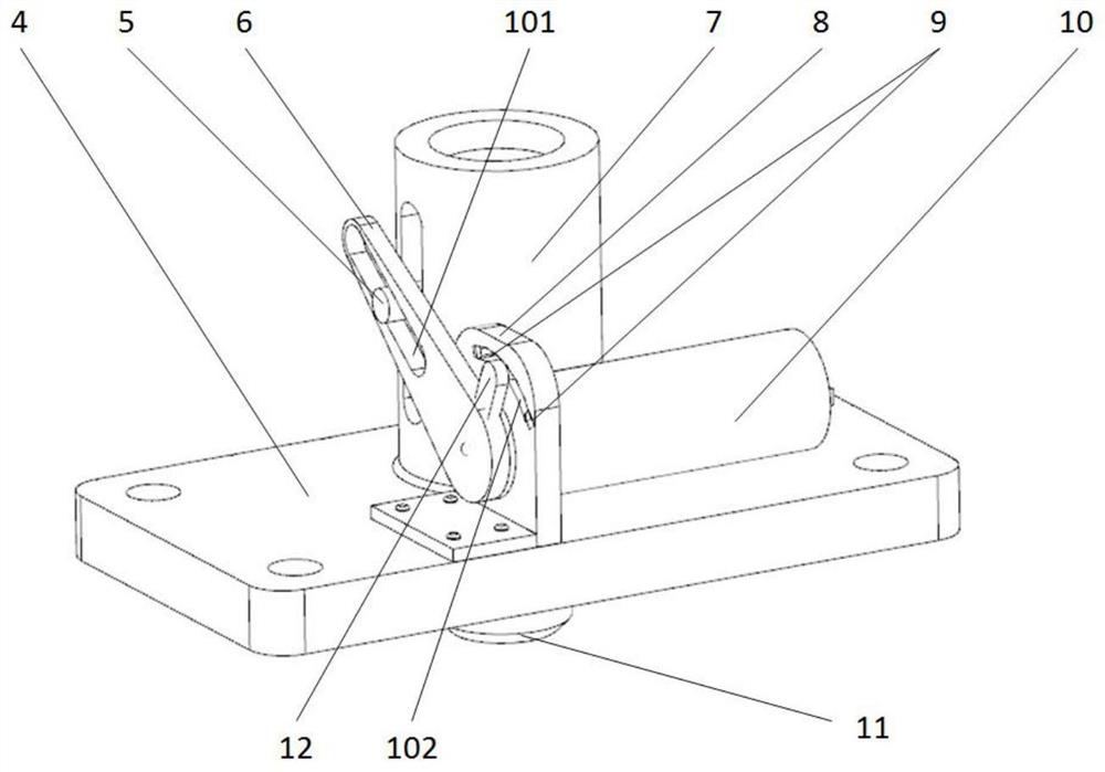
[0026] The inner wall on one side of the mounting frame 1 is connected to the side of the rotor 2...


PUM


Abstract

The invention discloses a turntable head locking mechanism, and relates to the related technical field of photoelectric equipment, the turntable head locking mechanism comprises a mounting rack of a U-shaped structure, a rotating head is mounted in the mounting rack through a rotating shaft, the inner wall of one side of the mounting rack is connected with the side surface of the rotating head through a locking mechanism, and the locking mechanism comprises a mounting plate fixed in the mounting rack; a guide cylinder and a support are fixed to the side face of the mounting plate, and a plug pin is movably mounted in the guide cylinder, a limiting rod groove is formed in the side face of the support, limiters are installed on the inner walls of the two ends of the limiting rod groove, a motor is installed on the side face of the support, a power output shaft of the motor is connected with the plug pin through a rotating arm, the side face of the rotating arm is connected with the limiting rod groove in an inserted mode through a plug pin, two guide rod grooves are formed in the outer wall of the guide cylinder, and the outer wall of the plug pin is movably connected with the guide rod grooves through guide rods. Through cooperative use of all the devices, the direction where the rotating head is located can be effectively locked, accidental deflection and vibration of the rotating head can be effectively avoided, and the accuracy of observing and aiming the situation outside the vehicle is guaranteed.

Description

technical field [0001] The invention relates to the related technical field of photoelectric equipment, in particular to a locking mechanism for the head of a turntable. Background technique [0002] With the continuous development of optoelectronic equipment, the turntable, as one of the most important roles in optoelectronic equipment, has been put forward higher requirements. [0003] The U-shaped turntable is used on the vehicle to monitor and aim at the target. It is mainly composed of a head and a U-shaped frame; among them, the head contains a variety of photoelectric equipment, and can be turned around in the azimuth through the U-shaped frame; the U-shaped The turntable is equivalent to the eyes of the driver of the car body, allowing the driver and operator to accurately observe the situation outside the car under the protection of the car body, which has high requirements for the performance of the U-shaped turntable; and the locking mechanism is the U A locking ...

Claims


Application Information

Patent Timeline
Patent Type & Authority Applications(China)
IPC IPC(8): B60R11/04H02K7/06
CPCB60R11/04B60R2011/0085B60R2011/0092H02K7/06
Inventor 杨晨詹江刘明东高雪军严伟彭恺魏传超
Owner 江苏北方湖光光电有限公司
Learn More