Braking energy recovery method and device for improving braking performance of whole vehicle

A braking energy recovery and braking energy technology, which is applied in electric braking systems, electric vehicles, vehicle components, etc., can solve the problems of uncoordinated braking force distribution ratio, low braking energy recovery efficiency, and insufficient braking performance, etc. problem, achieve the effect of suppressing vehicle pitching, improving braking performance and reducing start-up cost

Inactive Publication Date: 2021-08-27
TAIZHOU UNIV
View PDF7 Cites 0 Cited by
  • Summary
  • Abstract
  • Description
  • Claims
  • Application Information

AI Technical Summary

Problems solved by technology

[0004] The existing control methods for regenerative braking energy recovery of pure electric vehicles with rear axle drive are divided into: the optimal braking energy recovery control method based on the I curve (ideal braking curve) and the optimal braking energy recovery efficiency Braking energy recovery control method; the disadvantage of the braking energy recovery control method based on the best braking performance of the I curve is that the braking force of the front and rear axles is distributed according to the I curve, so there will be no braking force when the braking intensity is small. In the case of providing braking force, the braking energy recovery efficiency is too low; the disadvantage of the braking energy recovery control method with the best braking energy recovery efficiency is that the braking force of the car is provided by the braking force of the motor as much as possible, causing the front and rear axles The proportion of braking force distribution is not coordinated, resulting in insufficient braking performance and poor ride comfort of the car

Method used


Image

  • Braking energy recovery method and device for improving braking performance of whole vehicle
  • Braking energy recovery method and device for improving braking performance of whole vehicle
  • Braking energy recovery method and device for improving braking performance of whole vehicle

Examples


Embodiment Construction

[0024] The following will clearly and completely describe the technical solutions in the embodiments of the application with reference to the drawings in the embodiments of the application. Apparently, the described embodiments are only some of the embodiments of the application, not all of them. Based on the embodiments in this application, all other embodiments obtained by persons of ordinary skill in the art without making creative efforts belong to the scope of protection of this application.

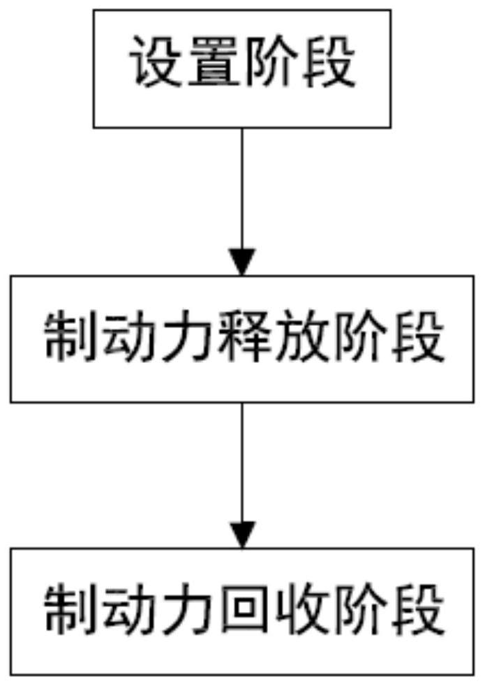
[0025] Such as figure 1 As shown, it shows a schematic flow chart of a braking energy recovery method for improving the braking performance of the vehicle provided by the embodiment of the present application. The braking energy recovery method for improving the braking performance of the vehicle provided by the embodiment of the present method may include the following steps:

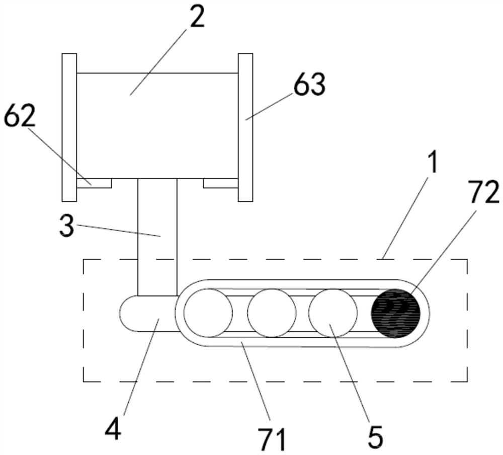
[0026] In the setting stage, a potential energy body 2 is connected horizontally above the chassis 1 of ...


PUM


Abstract

The invention relates to the field of braking energy recovery, and discloses a braking energy recovery method and system for improving the braking performance of a whole vehicle. The braking energy recovery system comprises a potential energy body, a lifter, a buffer linkage rod, a transmission gear set and a limiting device, the potential energy body is arranged above a chassis of the vehicle body, a space is reserved, the lifter is connected below the potential energy body, the lifter is connected with the chassis of the vehicle body through the buffer linkage rod, the transmission gear drives the buffer linkage rod to move, and the transmission gear set is used for transmitting mechanical energy of the potential energy body and the vehicle body; the limiting device is arranged above the potential energy body and used for fixing and releasing the potential energy body. Braking force generated when the vehicle brakes is recycled and converted into potential energy, the pressure of wheels on the ground is increased while the potential energy is converted, pitching of the vehicle is restrained, the braking performance is improved, and the braking distance is shortened; and meanwhile, when the vehicle is started, the driving force is improved by releasing the accumulated potential energy, the starting time is shortened, and the starting cost is reduced.

Description

technical field [0001] The invention relates to the field of braking energy recovery, in particular to a braking energy recovery method and device for improving the braking performance of a vehicle. Background technique [0002] As a new energy vehicle, pure electric vehicles are receiving more and more attention and promotion. As the only energy source for pure electric vehicles, power batteries provide energy to the motors. However, due to the bottleneck of battery technology, the energy density of batteries is currently low. The battery life of pure electric vehicles is not ideal. [0003] The energy recovery system is one of the effective means for pure electric vehicles to extend the battery life of the vehicle. Using the regenerative braking function of the motor, the kinetic energy lost during the braking process is converted into electrical energy through the motor and reused, which can realize the overall energy efficiency of the pure electric vehicle. Reduce power...

Claims


Application Information

Patent Timeline
Patent Type & Authority Applications(China)
IPC IPC(8): B60L7/10
CPCB60L7/10
Inventor 李宁
Owner TAIZHOU UNIV
Why Eureka
Try Eureka