Flyback converter and its control method
A technology of flyback converter and controller, which is applied in the direction of control/regulation system, conversion equipment with intermediate conversion to AC, DC power input conversion to DC power output, etc., which can solve the problem of increasing system cost and size, flyback conversion To reduce the cost and size, optimize the circuit structure, and expand the application range
- Summary
- Abstract
- Description
- Claims
- Application Information
AI Technical Summary
Problems solved by technology
Method used
Image

Examples
Embodiment 1
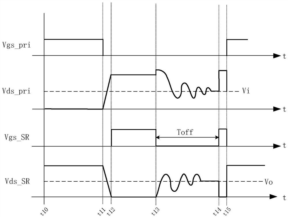
[0111] In this embodiment, the flyback converter works in the DCM mode, and the timing waveforms of some control signals in the flyback converter in the DCM mode are as follows image 3 shown.
[0112] In this embodiment, the timing signal generated by the control signal generating unit 43 can control the synchronous rectifier SR to turn on twice in one switching cycle (the first turn-on corresponds to the time period t12-t13, and the second turn-on corresponds to the time period t14-t15 ), at the same time, after the control synchronous rectifier SR is turned on for the first time, compared with the normal control sequence, the synchronous rectifier SR will be turned off earlier.
[0113] In this embodiment, the target time parameter corresponds to the interval time Toff between the first turn-off of the synchronous rectifier SR to the second turn-on, that is, the time period t13 to t14 . Therefore, in this embodiment, the first functional relationship stored separately in t...
Embodiment 2
[0125] In this embodiment, the flyback converter works in the BCM mode, and the timing waveforms of some control signals in the flyback converter in the BCM mode are as follows: Figure 4 shown.
[0126] In this embodiment, the timing signal generated by the control signal generating unit 43 can control the synchronous rectifier SR to be turned off with a delay in one switching cycle.
[0127] In this embodiment, the synchronous rectifier controller 4 controls the body diode of the synchronous rectifier SR to conduct in the interval after the power switch SW is turned off to before the synchronous rectifier SR is turned on in each cycle. And the target time parameter corresponds to the conduction time td of the body diode of the synchronous rectifier SR, that is, the time period t22-t23. Therefore, in this embodiment, the first functional relationship stored separately in the second computing unit 42, or the first functional relationship stored in both the first computing uni...
Embodiment 3
[0140] In this embodiment, the flyback converter works in the BCM mode, and the timing waveforms of some control signals in the flyback converter in the BCM mode are as follows: Figure 5 shown.
[0141] In this embodiment, the timing signal generated by the control signal generating unit 43 can control the synchronous rectifier SR to turn on twice in one switching cycle (the first turn-on corresponds to the time period t32-t33, and the second turn-on corresponds to the time period t34-t35 ), at the same time, the interval between the two turn-ons of the control synchronous rectifier SR (corresponding to the time period t33-t34) is less than the preset threshold, which can be equivalent to the normal control sequence of the synchronous rectifier SR. is turned off once during the turn-on period.
[0142] In this embodiment, the target time parameter corresponds to the first turn-on time T1 (corresponding to the time period t32-t33) or the second turn-on time T2 (corresponding ...
PUM
 Abstract
Description
Claims
Application Information
 - R&D
- Intellectual Property
- Life Sciences
- Materials
- Tech Scout
- Unparalleled Data Quality
- Higher Quality Content
- 60% Fewer Hallucinations
Browse by: Latest US Patents, China's latest patents, Technical Efficacy Thesaurus, Application Domain, Technology Topic, Popular Technical Reports.
© 2025 PatSnap. All rights reserved.Legal|Privacy policy|Modern Slavery Act Transparency Statement|Sitemap|About US| Contact US: help@patsnap.com