
Unmanned aerial vehicle-mounted XRF and image fusion lithology identification system and method

A technology of lithology recognition and image fusion, which is applied in character and pattern recognition, scene recognition, neural learning methods, etc. Sex recognition is quick and easy, protection is safe, and the effect is simple to operate

Active Publication Date: 2021-08-24
SHANDONG UNIV
View PDF8 Cites 3 Cited by
  • Summary
  • Abstract
  • Description
  • Claims
  • Application Information

AI Technical Summary

Problems solved by technology

The identification under the thin-section microscope requires difficult grinding operations, and there are large errors in naked eye identification, which cannot meet the requirements of direct on-site lithology identification in remote areas
Relying on a single detection method for lithology identification has been widely used in engineering, but relying on a single method for lithology identification often cannot meet the requirements of image and element information at the same time, and the lithology identification results often have certain errors
For example: Quartzite and limestone cannot be identified based on image information only, and element information is needed at this time
[0005] Since the image data is much higher than the element data by many orders of magnitude, the two are fused with each other, which is very easy to cause data flooding, and then the data cannot be processed, and the lithology identification information cannot be obtained, which affects the accuracy of lithology identification
The inventor found that the existing method of image and XRF fusion is to reduce the image to a one-dimensional vector, and then splicing it with the one-dimensional XRF vector, and the image dimensionality reduction processing operation may easily lead to the loss of some important parts of the image. information, thus affecting the accuracy of lithology identification

Method used


Image

  • Unmanned aerial vehicle-mounted XRF and image fusion lithology identification system and method
  • Unmanned aerial vehicle-mounted XRF and image fusion lithology identification system and method
  • Unmanned aerial vehicle-mounted XRF and image fusion lithology identification system and method

Examples


Embodiment Construction

[0039] The present invention will be further described below in conjunction with the accompanying drawings and embodiments.

[0040] It should be noted that the following detailed description is exemplary and intended to provide further explanation of the present invention. Unless defined otherwise, all technical and scientific terms used herein have the same meaning as commonly understood by one of ordinary skill in the art to which this invention belongs.

[0041] It should be noted that the terminology used here is only for describing specific embodiments, and is not intended to limit exemplary embodiments according to the present invention. As used herein, unless the context clearly dictates otherwise, the singular is intended to include the plural, and it should also be understood that when the terms "comprising" and / or "comprising" are used in this specification, they mean There are features, steps, operations, means, components and / or combinations thereof.

[0042] In...


PUM


Abstract

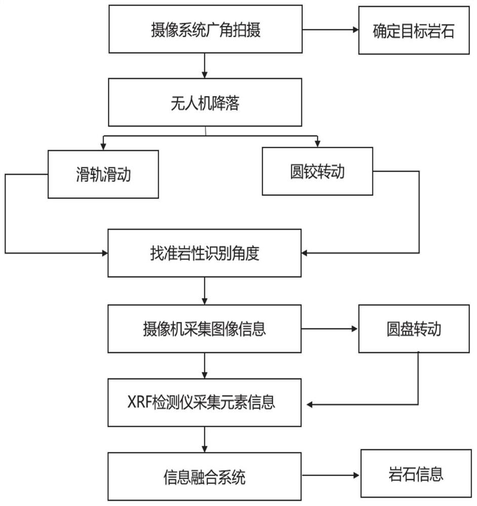
The invention belongs to the technical field of lithology identification, and provides an unmanned aerial vehicle-mounted XRF and image fusion lithology identification system and method. The lithology identification system comprises an information acquisition system, an information fusion system and a lithology identification system. The information acquisition system, the information fusion system and the lithology identification system are all carried on the unmanned aerial vehicle; the information acquisition system comprises an XRF detection system and an image acquisition system which are used for detecting element information and image information of rocks in a set area and transmitting the element information and the image information to the information fusion system; the information fusion system is used for expanding the element information into three-dimensional element information and fusing the three-dimensional element information with three-dimensional image information to obtain fusion information; the deep features of the image information and the shallow features of the fusion information are fused step by step to obtain a fusion feature map; and the lithology identification system is used for identifying the lithology of the rock in the set area based on the fused feature map.

Description

technical field [0001] The invention belongs to the technical field of lithology identification, and in particular relates to a lithology identification system and method of unmanned aerial vehicle-mounted XRF and image fusion. Background technique [0002] The statements in this section merely provide background information related to the present invention and do not necessarily constitute prior art. [0003] Lithology identification is beneficial to understand the geological conditions of a region, or provide a data basis for geological modeling in a certain region. The geological environment in the field is complex, with steep mountains and steep terrain. Due to the limitation of the geographical environment, professional staff cannot reach or it is inconvenient to carry out geological identification and other work. Even if professionals in some dangerous areas can reach, the safety of the staff cannot be guaranteed. In addition, staff need to bring relevant instruments ...

Claims


Application Information

Patent Timeline
IPC IPC(8): G06K9/00G06K9/46G06K9/62G06N3/04G06N3/08
CPCG06N3/08G06V20/13G06V10/44G06N3/045G06F18/253
Inventor 林鹏李轶惠石恒许广璐邵瑞琦马文谢辉辉
Owner SHANDONG UNIV
Learn More