
Fluid pressure measuring device based on fluid statics principle

A technology of hydrostatics and fluid pressure, which is applied in the direction of fluid pressure measurement, measuring device, and measurement of fluid pressure using liquid as a pressure-sensitive medium. problems, to avoid constant compression, increase the measurement range, and reduce the occupied space

Active Publication Date: 2021-08-24
力创科技股份有限公司
View PDF8 Cites 0 Cited by
  • Summary
  • Abstract
  • Description
  • Claims
  • Application Information

AI Technical Summary

Problems solved by technology

[0002] The fluid pressure gauge is used to measure the pressure of the fluid. The traditional fluid pressure gauge is divided into two types: liquid type and metal type. The liquid type pressure gauge is based on the principle of hydrostatics, and the pressure generated by the self-weight of the liquid column is balanced with the measured pressure. Due to the limited height of the measuring tube of the liquid manometer, the liquid column cannot rise indefinitely, so the liquid manometer can only be used to measure a small pressure, when it is necessary to measure a large pressure When, you need to use the metal pressure gauge
[0003] The commonly used metal pressure gauge is a spring pressure gauge, which uses the pressure change in the spring tube to make the free end of the tube displace, and the displacement drives the pointer on the dial to deflect through the transmission mechanism, so as to achieve the pressure measurement effect, but the spring tube is affected by its own elasticity. Limit influence, elastic deformation is small, and the span of the measured fluid pressure value is not large. Based on this, some devices have made improvements to the above problems, using the elastic force of the coil spring and the transmission of the rack and pinion to realize the measurement of the large-span pressure value, but the above-mentioned The device still has the following disadvantages:
[0004] 1. When the elastic coefficient of the above-mentioned helical spring is relatively small, in order to realize the pressure measurement of a large span, the helical spring needs to be designed to be very long, so as to bear the high pressure of the measured fluid, which will take up a lot of room for design
[0005] 2. When the elastic coefficient of the above-mentioned helical spring is relatively large, the length of the helical spring can be greatly shortened, but when the pressure value of the measured fluid is small, the deformation of the helical spring is correspondingly small. When the helical spring When the amount of deformation is less than the backlash between the rack and pinion, the rack that moves slightly with the coil spring will not be able to push the gear to rotate, and the device will not be able to measure the pressure of the measured fluid at this time
[0006] 3. Due to the transmission of rack and pinion, it is necessary to leave enough space for the rack when designing the device, which further increases the occupied space of the device and reduces the adaptability of the device to various application environments

Method used


Image

  • Fluid pressure measuring device based on fluid statics principle
  • Fluid pressure measuring device based on fluid statics principle
  • Fluid pressure measuring device based on fluid statics principle

Examples


Embodiment 1

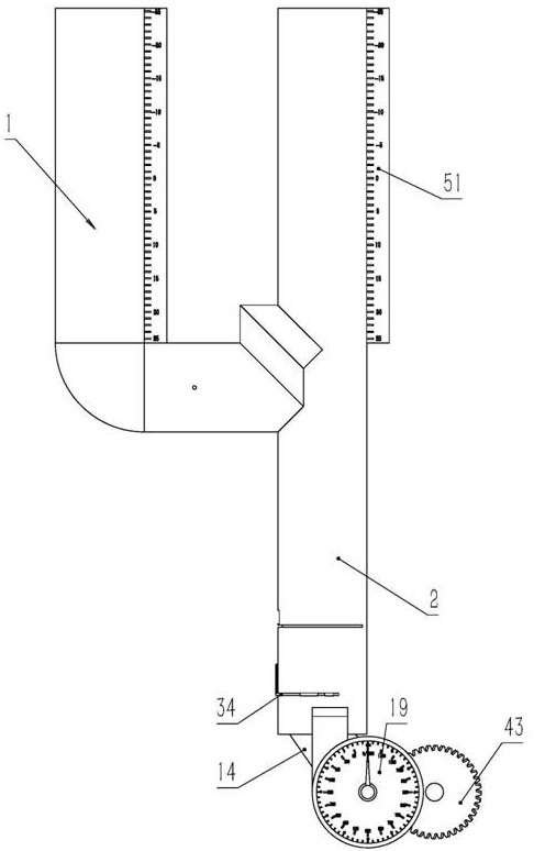
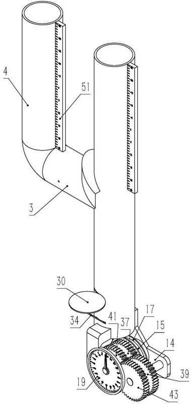
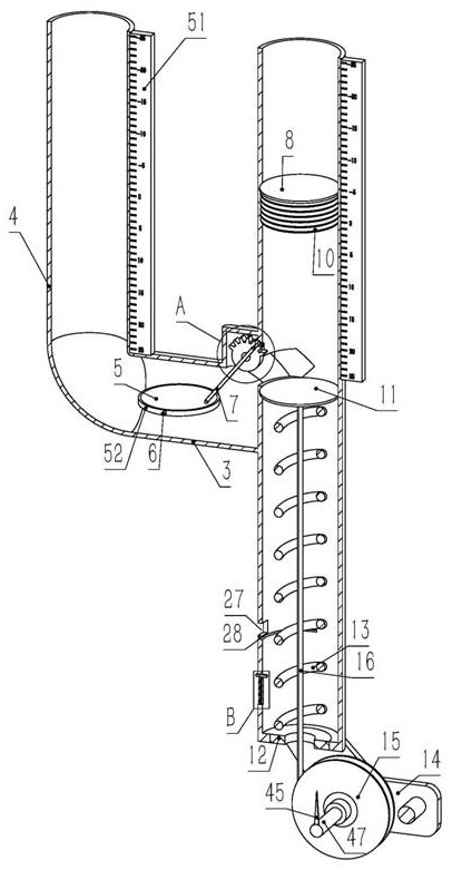
[0031]Embodiment 1. A fluid pressure measuring device based on the principle of hydrostatics, comprising a pressure measuring tube, the pressure measuring tube includes a U-shaped pipe 1 and a relief pipe 2, and the U-shaped pipe 1 is composed of a transition pipe section 3 arranged transversely It is composed of two vertical measuring pipe sections 4, and the two measuring pipe sections 4 are arranged side by side and placed on the left and right sides of the transition pipe section 3 respectively. The left and right ends of the transition pipe section 3 correspond to the two measuring pipe sections 4 one by one. The end of the pipe is connected with the lower end of the corresponding measuring pipe section 4, that is, the two measuring pipe sections 4 are connected through the transition pipe section 3, the relief pipe 2 is coaxial with the measuring pipe section 4 on the right side of the transition pipe section 3, and the inner diameter of the relief pipe 2 and the transitio...

Embodiment 2

[0033] Embodiment 2, on the basis of Embodiment 1, the positioning shaft 6 is set along the front-to-back direction, the gear mechanism includes an incomplete gear 20 placed in the transition pipe section 3, and the axis of the incomplete gear 20 is set along the front-to-back direction. The complete gear 20 is placed on the upper right side of the transition pipe section 3, and the transition pipe section 3 has a fixed shaft 21 pierced in the inner hole of the incomplete gear 20, and the side wall of the fixed shaft 21 is provided with an arc-shaped limit Slot 22, the arc-shaped path of the limiting groove 22 is coaxial with the fixed shaft 21, and the incomplete gear 20 has a limiting block 23 placed in the limiting groove 22 and slidingly matched with the limiting groove 22, forming an incomplete The limit rotation connection between the complete gear 20 and the transition pipe section 3, at this time the limit block 23 is located at the start position of the limit groove 22...

Embodiment 3

[0034] Embodiment 3, on the basis of Embodiment 1, a pressure relief hole 27 close to the bottom end of the relief pipe 2 is opened on the side wall of the relief pipe 2. When the measured fluid pressure exceeds the range of the dial 19, Under the action of the measured fluid pressure, the pressure plate 8 will pass over the pressure relief hole 27, so that the measured fluid pressure will be released from the pressure relief hole 27, so as to prevent the device from being damaged due to high pressure.


PUM


Abstract

The invention discloses a fluid pressure measuring device based on a fluid statics principle, and effectively solves the problem of weak adaptability caused by defects of an existing fluid pressure gauge during design. Two fluid pressure measuring methods are adoped to measure fluid pressure, and the two methods do not interfere with each other but complement each other, and can both realize measurement of low-pressure / micro-pressure fluid and realize measurment of high-pressure fluid, so that the device has high adaptability; and overload breakage of the transmission spring is effectively prevented by a protection door when the impact load of the measured fluid is large, so that the device is protected, and the service life of the device is prolonged.

Description

technical field [0001] The invention relates to the field of pressure measuring equipment, in particular to a fluid pressure measuring device based on the principle of fluid statics. Background technique [0002] The fluid pressure gauge is used to measure the pressure of the fluid. The traditional fluid pressure gauge is divided into two types: liquid type and metal type. The liquid type pressure gauge is based on the principle of hydrostatics, and the pressure generated by the self-weight of the liquid column is balanced with the measured pressure. Due to the limited height of the measuring tube of the liquid manometer, the liquid column cannot rise indefinitely, so the liquid manometer can only be used to measure a small pressure, when it is necessary to measure a large pressure , you need to use one of the metal pressure gauges. [0003] The commonly used metal pressure gauge is a spring pressure gauge, which uses the pressure change in the spring tube to make the free ...

Claims


Application Information

Patent Timeline
Patent Type & Authority Applications(China)
IPC IPC(8): G01L7/18G01L19/06G01L19/16G01L19/10
CPCG01L7/18G01L7/182G01L7/185G01L19/0618G01L19/16G01L19/10
Inventor 张健
Owner 力创科技股份有限公司
Learn More