
Flexible solar wing unfolding mechanism with high unfolding-folding ratio

A deployment mechanism and flexible technology, applied in the aerospace field, can solve the problems of poor reliability of the solar wing deployment mechanism, large size of the deployment mechanism, complex mechanical structure, etc., and achieve a simple and uncomplicated mechanical structure, saving launch costs, and high expansion-to-receive ratio. Effect

Pending Publication Date: 2021-08-24
CHANGGUANG SATELLITE TECH CO LTD
View PDF1 Cites 4 Cited by
  • Summary
  • Abstract
  • Description
  • Claims
  • Application Information

AI Technical Summary

Problems solved by technology

[0005] After careful research, it is found that the mechanical structure of the deployment mechanism disclosed in the prior art is complex and easily damaged, and the deployment mechanism occupies a large volume in the folded state, and the reliability of the solar wing deployment mechanism is poor due to too many parts
[0006] As mentioned above, based on the above technical problems, those skilled in the art urgently need to address the complex structure, large mass, high cost and most of the flexible solar wing deployment mechanisms in the prior art, which are only suitable for ultra-high-power spacecraft, etc. Problem: To develop a new type of solar wing deployment mechanism with a large unfolded size and light weight and a small folded size with a high aspect ratio

Method used


Image

  • Flexible solar wing unfolding mechanism with high unfolding-folding ratio
  • Flexible solar wing unfolding mechanism with high unfolding-folding ratio
  • Flexible solar wing unfolding mechanism with high unfolding-folding ratio

Examples


Embodiment Construction

[0101] In order to enable those skilled in the art to better understand the technical solutions of the present invention, the present invention will be further described in detail below in conjunction with the accompanying drawings.

[0102] see Figure 3 to Figure 10 shown;

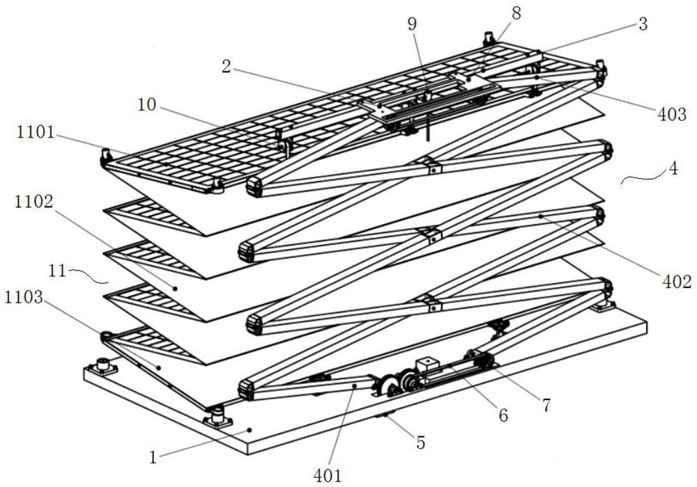
[0103] A flexible solar wing deployment mechanism with a high expansion-to-contraction ratio of the present invention, the deployment mechanism includes:

[0104] bottom plate 1;

[0105] a scissor bar assembly 4 integrated into the base plate 1; and

[0106] The solar blanket assembly 11 connected with the scissor bar assembly 4;

[0107] Expanding bodies also include:

[0108] The drive assembly 5 integrated in the base plate 1;

[0109] The driving assembly 5 has a driving motor 501 and a transmission gear 503 that is transmitted with the driving motor 501, and the transmission gear 503 extends to the upper part of the bottom plate 1;

[0110] The drive assembly 5 is in transmission connection w...


PUM


Abstract

The invention discloses a flexible solar wing unfolding mechanism with a high unfolding-folding ratio. The flexible solar wing unfolding mechanism comprises a bottom plate, a shear fork rod assembly, a top plate and a solar blanket assembly; the unfolding mechanism further comprises a driving assembly integrated on the bottom plate; the driving assembly is provided with a driving motor and a transmission gear, and the transmission gear extends to the upper part of the bottom plate; and the driving assembly is in transmission connection with the shear fork rod assembly through the transmission gear and drives the shear fork rod assembly to be unfolded so as to drive the solar blanket assembly to be unfolded. The unfolding mechanism is simple in structure, high in reliability and small in mass; most structural parts in the mechanism are made of spaceflight-grade hard aluminum alloy and carbon fiber composite materials, the mechanical structure is simple and not numerous and jumbled, and the structural parts are subjected to lightweight design improvement on the premise that the strength and vibration requirements are guaranteed; and the unfolding mechanism is low in manufacturing cost and material price, structural parts are simple in structure and convenient to manufacture, the shear fork rod assembly drives the solar blanket assembly to move, and the unfolding mechanism has the advantages of being light in weight, small in folding size, large in unfolding span and high in unfolding and folding ratio.

Description

technical field [0001] The invention relates to the field of aerospace technology, in particular to a flexible solar wing deployment mechanism with a high expansion-to-contraction ratio, which is suitable for folding flexible solar wings. Background technique [0002] The solar wing deployment mechanism is an important part of the solar wing, which is mainly used for the constriction, deployment and support of the solar blanket. The role of the unfolding mechanism is to gather the solar blanket to meet the stiffness requirements and launch envelope during the satellite launch phase, and to ensure that it does not cause violent vibrations to damage the solar blanket or other stand-alone units on the satellite. After entering orbit, the solar blanket can be smoothly unfolded and locked. Provide support for the unfolded solar blanket, and ensure that the solar blanket does not hook and interfere with various parts of the satellite during the unfolding process, and also meet the...

Claims


Application Information

Patent Timeline
Patent Type & Authority Applications(China)
IPC IPC(8): B64G1/44
CPCB64G1/222B64G1/443
Inventor 于济菘臧宏达张道威谷松孔林张雷
Owner CHANGGUANG SATELLITE TECH CO LTD
Learn More