Flaring and shaping device for joints of flush plastic pipes
A technology for plastic pipes and sizing devices, which is applied to machine tools, manufacturing tools, grinders and other directions suitable for grinding the edges of workpieces, can solve the problems of difficulty in flaring, manual grinding, and reduced sealing performance of plastic pipes, and achieves convenient use and avoids problems. The effect of lifting and improving construction efficiency
- Summary
- Abstract
- Description
- Claims
- Application Information
AI Technical Summary
Problems solved by technology
Method used
Image
Examples
Embodiment 1
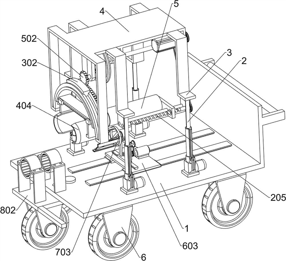
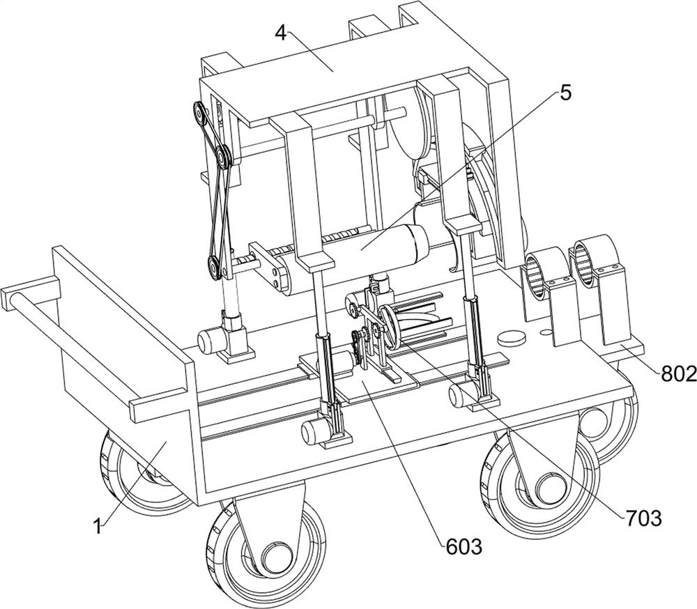
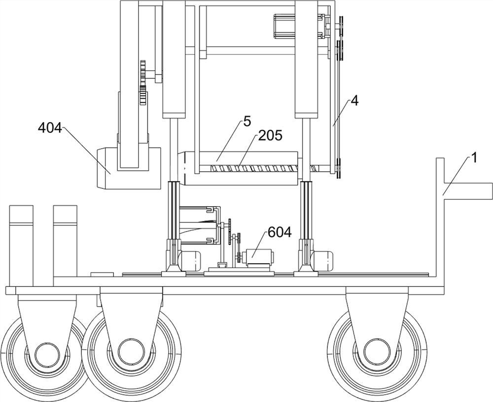
[0040] A flaring and shaping device for joints of flush plastic pipes, such as Figure 1-9 As shown, it includes a vehicle frame 1, a driving member 2, a first connecting plate 3, a flaring frame 4, a flaring device 5, a first traveling wheel 6, a flaring driving mechanism, a reciprocating rotation mechanism and a pipe clamping mechanism; Four groups of driving parts 2 are symmetrically installed on the vehicle frame 1; the tops of the movable rods of the four groups of driving parts 2 are fixedly connected with a group of first connecting plates 3; The port frame 4 includes a horizontal plate 41, a first vertical plate 42, a second vertical plate 43, a third vertical plate 44, a fourth vertical plate 45, a fifth vertical plate 46, a sixth vertical plate 47 and a seventh vertical plate 48; the left rear side of the horizontal plate 41 of the flared frame 4 is connected with the first vertical plate 42; the left front side of the horizontal plate 41 of the flared frame 4 is con...
Embodiment 2
[0051] like figure 1 and Figure 17-19As shown, a support mechanism is also included, and the support mechanism includes a guide U-shaped plate 801, a support plate 802, a push rod 803, an insertion rod 804, a second traveling wheel 805, a first clamping assembly and a second clamping assembly; Two sets of symmetrically distributed guide U-shaped plates 801 are connected by bolts on the lower surface of the frame 1; a support plate 802 is slidingly connected between the two sets of guide U-shaped plates 801; a push rod 803 is fixedly connected to the left side of the support plate 802; There are at least two jacks on the support plate 802, the support plate 802 is inserted with an insertion rod 804 through the jack, and the vehicle frame 1 is inserted into the insertion rod 804 through the jack; the left side of the support plate 802 lower surface is fixedly connected with a The second traveling wheel 805; the first clamping assembly is installed on the left side of the upper...
Embodiment 3
[0056] like figure 1 and Figure 10-16 As shown, a burr removal mechanism is also included, and the burr removal mechanism includes a second electric slide rail 601, a second electric slider 602, a third connecting plate 603, a second motor 604, a fourth connecting plate 605, and a fourth pulley 606 , the third rotating rod 607, the fifth pulley 608, the third gear 609, the third electric slide rail 610, the third electric slider 611, the connecting frame 612, the fourth rotating rod 613, the fourth gear 614, the connecting rod 615 and Grinder 616; two sets of second electric slide rails 601 symmetrically distributed are installed above the vehicle frame 1; two sets of second electric slide rails 601 are slidingly connected with a set of second electric slide blocks 602 on the outer surfaces; two sets of second electric slide rails A third connecting plate 603 is fixedly connected above the block 602; a second motor 604 is fixedly connected on the right side above the third c...
PUM
 Abstract
Description
Claims
Application Information
 - R&D Engineer
- R&D Manager
- IP Professional
- Industry Leading Data Capabilities
- Powerful AI technology
- Patent DNA Extraction
Browse by: Latest US Patents, China's latest patents, Technical Efficacy Thesaurus, Application Domain, Technology Topic, Popular Technical Reports.
© 2024 PatSnap. All rights reserved.Legal|Privacy policy|Modern Slavery Act Transparency Statement|Sitemap|About US| Contact US: help@patsnap.com


