Automatic detection method and device for depth of piston clamp spring groove

An automatic detection device and automatic detection technology, which is applied in the direction of measuring devices, optical devices, instruments, etc., can solve the problems of high labor costs, increased manual detection, and manual detection prone to errors

Pending Publication Date: 2021-08-20
ZHAOQING HONDA FOUNDRY CO LTD
View PDF0 Cites 0 Cited by
  • Summary
  • Abstract
  • Description
  • Claims
  • Application Information

AI Technical Summary

Problems solved by technology

[0003] One of the purposes of the present invention is to provide a piston circlip groove in order to solve the problems of manual detection that is prone to errors, difficult to guarantee product quality, need to increase special manual manual detection, and high labor cost in the production of piston circlip grooves in the prior art. The deep automatic detection method has outstanding substantive characteristics and significant technological progress such as mechanical automatic detection product quality assurance, no need to increase special manual manual detection, low labor cost, etc.
[0004] The second purpose of the present invention is to provide a piston circlip groove in order to solve the problems of manual detection that is prone to errors, difficult to guarantee product quality, need to increase special manual manual detection, and high labor cost in the production of piston circlip grooves in the prior art. The deep automatic detection device has outstanding substantive features and significant technological progress such as mechanical automatic detection product quality assurance, no need to increase special manual manual detection, and low labor cost.

Method used


Image

  • Automatic detection method and device for depth of piston clamp spring groove
  • Automatic detection method and device for depth of piston clamp spring groove
  • Automatic detection method and device for depth of piston clamp spring groove

Examples


specific Embodiment 1

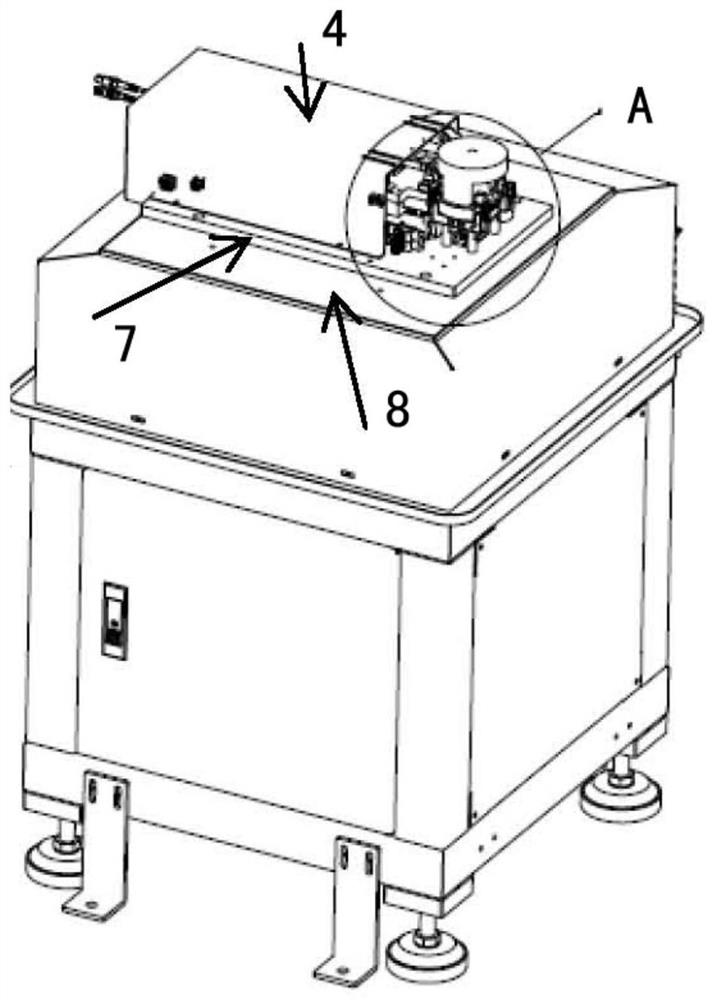
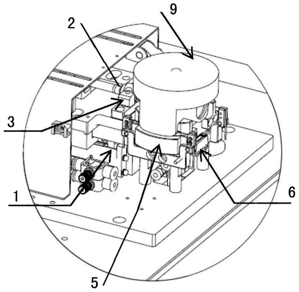
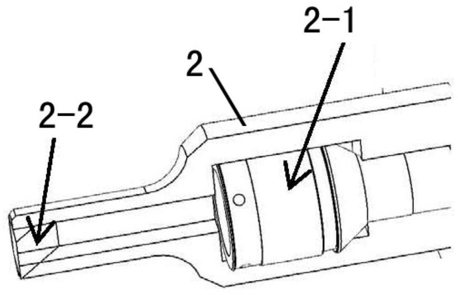
[0035] refer to Figure 1 to Figure 3 The automatic detection device for the depth of the piston circlip groove involved in this embodiment includes a servo motor module 1, a laser detector 2, a laser detection fixture 3, a workpiece fixing fixture 5 and an air detection device 6, the servo motor module 1, Laser detector 2, laser detection fixture 3, workpiece fixing fixture 5 and air detection device 6 are arranged on fixed base 7; It performs blowing and drying; the drive output end of the servo motor module 1 is connected to the laser detection head 2-1 of the laser detector 2 to drive the laser detection head 2-1 to the detection position; the workpiece fixing fixture 5 has a limit fixing structure, To limit and fix the workpiece; the laser detector 2 is fixedly arranged in the laser detection fixture 3, and its laser detection head 2-1 faces the piston circlip groove of the workpiece, emits and receives reverse light to the piston circlip groove, The reflected light rece...


PUM


Abstract

The invention relates to an automatic detection method and device for the depth of a piston clamp spring groove, and the device is characterized in that the device comprises a servo motor module, a laser detector, a laser detection clamp, a workpiece fixing clamp, and a gas detection device, which are disposed on a fixed pedestal. The gas detection device is arranged beside the workpiece fixing clamp, the driving output end of the servo motor module is connected with a laser detection head of the laser detector, the workpiece fixing clamp is provided with a limiting and fixing structure, the laser detector is fixedly arranged in the laser detection clamp, and the laser detection head of the laser detector faces a piston clamp spring groove of a workpiece. Reflected light received by the laser detector forms a depth detection signal of the piston clamp spring groove on the laser sensor, and the signal output end of the laser sensor is connected with the signal input end of the computer processor, so that the laser type automatic detection structure for the depth of the piston clamp spring groove is formed. The method has the advantages of mechanically and automatically detecting product quality, being low in labor cost and the like.

Description

technical field [0001] The invention relates to an automatic detection method and device for the depth of a piston ring groove. It belongs to the technical field of manufacturing equipment for automobiles and their accessories. Background technique [0002] In the existing production technology, a piston needs to go through nine processing steps from raw material to finished product. Wherein, the piston pin hole is processed at the station of the fourth processing procedure, and the ring groove is formed at the same time. The snap ring groove, as the name implies, is exactly the groove where the snap ring is placed. The piston circlip is a kind of fastener, and the circlip groove of the piston pin hole plays a role in preventing the axial movement of the piston pin. In the prior art, due to the occasional poor size of the circlip groove during the processing process, there is no special testing equipment, so it is necessary to use manual full size inspection to control pr...

Claims


Application Information

Patent Timeline
IPC IPC(8): G01B11/22
CPCG01B11/22
Inventor 黄荣权
Owner ZHAOQING HONDA FOUNDRY CO LTD
Why Eureka
Try Eureka