Parking device for robot

A robot and mounting plate technology, which is applied in the field of robot parking devices, can solve the problems of difficult to balance the carrying capacity of the chassis, the large walking space, and the large size of the base, so as to achieve convenient obstacle avoidance and traffic, high carrying capacity, Good shock absorption effect

Pending Publication Date: 2021-08-20
STATE GRID ZHEJIANG ELECTRIC POWER CO LTD JIAXING POWER SUPPLY CO +1
View PDF13 Cites 0 Cited by
  • Summary
  • Abstract
  • Description
  • Claims
  • Application Information

AI Technical Summary

Problems solved by technology

[0006] In the prior art, most of the robots are driven by the auxiliary driving wheel of the universal wheel. The base size is large, the cost is high, and the required walking space is large. It is difficult to balance the carrying capacity of the chassis and the traffic capacity of the robot.

Method used


Image

  • Parking device for robot
  • Parking device for robot
  • Parking device for robot

Examples


Embodiment 1

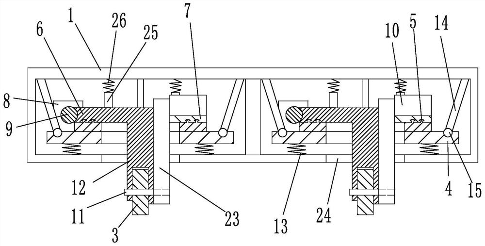
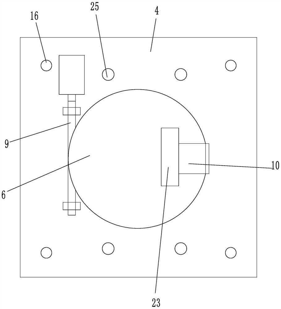
[0029] Such as figure 1 and image 3As shown, a parking device for a robot is characterized in that it includes a chassis, four driving wheels 3 are arranged on the underside of the chassis, and the four driving wheels 3 are located at the four corners of the chassis, the chassis includes a frame 1, and the frame 1 is a cuboid structure, Frame 1 includes upper and lower frame plates, a cavity is formed between the two frame plates, the edges of the two frame plates are connected by side plates, reinforcing ribs or beams can be set on the lower side of the upper frame plate to improve the load-bearing capacity of the frame plate . A support column is provided between the upper frame plate and the lower frame plate. A mounting plate 4 is arranged in the frame 1, and an annular guide rail 5 is arranged on the mounting plate 4, and the annular guide rail 5 is circular. A slider 6 and a motor base 7 are slid on the annular guide rail 5, and the two ends of the slider 6 are synch...

Embodiment 2

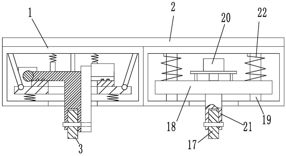
[0032] A robot parking device, such as figure 2 As shown, the shape of the chassis is a cuboid. The difference between embodiment 2 and embodiment 1 is that there are three driving wheels 3, two of which are arranged on a diagonal line on the lower side of the chassis, and the lower side of the chassis A guide wheel 17 and another driving wheel 3 are arranged on the other diagonal, that is, image 3 One of the four drive wheels 3 shown is replaced by a guide wheel 17 . The structure and size of guide wheel 17 are identical with driving wheel 3. A lifting plate 18 is arranged in the frame 1, and a rotating motor 20 is fixedly arranged on the lifting plate 18. The rotating motor 20 is connected with a rotary shaft 21, and the rotary shaft 21 is connected with the lifting plate 18 in rotation. The wheel 17 is arranged in the open slot through bearing rotation, and the frame 1 is provided with a vertically arranged lifting shaft 19, and the lifting plate 18 is slidably arranged...

Embodiment 3

[0035] A robot parking device, such as Figure 7 As shown, the difference between Embodiment 3 and Embodiment 1 is that the ring guide rail 5 is arranged on the underside of the mounting plate 4, and the ring guide rail 5 is arranged downward, so that the power assembly, the slider 6 and the motor seat 7 are also arranged in the ring On the lower side of the slide rail, after the chassis is formed, the annular guide rail 5 and the slide block 6 act under pressure, which has higher stability.


PUM


Abstract

The invention discloses a parking device for a robot. The parking device is characterized by comprising a chassis, wherein a plurality of drive wheels are arranged at the lower side of the chassis; the chassis comprises a framework; a mounting plate is arranged in the framework; an annular guide rail is arranged on the mounting plate; a slide block and a motor base are arranged on the annular guide rail in a sliding mode; the two ends of the slide block are synchronously connected with the motor base; the slide block is equipped with a power assembly; the motor base is matched with a drive motor of the drive wheels; the drive motor is equipped with a matched transmission assembly; the drive wheel comprises a rotary shaft connected with the drive wheel; the transmission assembly is matched with the rotary shaft; the outside of the rotary shaft is matched with a rotary shaft base; the rotary shaft base is fixedly connected to the lower side of the slide block; and a damping spring is arranged between the mounting plate and the framework. Each drive wheel is independently driven and controlled in steering, and at least three drive wheels bear pressure, so that drive force is stable; and the chassis internal structure is integrated, so that longitudinal bearing ability is high, stability is high and passing and obstacle-crossing ability of the robot is improved.

Description

technical field [0001] The present application relates to the technical field of industrial robots, in particular to a parking device for a robot. Background technique [0002] The security machine inspection robot, also known as the security robot, is semi-autonomous, autonomous or assists human beings under the complete control of human beings. [0003] Robots that complete safety protection work; security inspection robots, as a subdivision of the robot industry, are based on [0004] For actual production and living needs, it is used to solve potential safety hazards, patrol monitoring and disaster early warning, etc. With the rapid development of the economy, the scale of the power system continues to expand, and there are more and more corresponding urban power distribution rooms and distribution cabinets. In order to ensure the power supply, it is necessary to invest a lot of manpower and financial resources in inspection and maintenance, and the cost of manual maint...

Claims


Application Information

Patent Timeline
Patent Type & Authority Applications(China)
IPC IPC(8): B25J5/00B25J11/00B25J19/00
CPCB25J5/007B25J11/00B25J19/0091
Inventor 韩中杰孙献春周刚盖立梅汤玲艳王春林李玲娟卢思瑶
Owner STATE GRID ZHEJIANG ELECTRIC POWER CO LTD JIAXING POWER SUPPLY CO
Why Eureka
Try Eureka