
Auxiliary heat dissipation device for computer hardware

A computer hardware and auxiliary heat dissipation technology, which is applied in the computer field, can solve problems such as unsatisfactory heat dissipation effect, difficulty in parrying the auxiliary heat dissipation device of the notebook computer, and sudden increase of the operating temperature of the notebook computer.

Inactive Publication Date: 2021-08-17
陕西工业职业技术学院
View PDF0 Cites 0 Cited by
  • Summary
  • Abstract
  • Description
  • Claims
  • Application Information

AI Technical Summary

Problems solved by technology

[0004] However, the heat dissipation effect of this auxiliary heat dissipation method is still not satisfactory, especially when using a notebook computer to run applications that have certain requirements for configuration (such as large office software, drawing tools, large client games, etc.), usually due to the high CPU Occupancy, the high occupation of the GPU leads to a sharp increase in the operating temperature of the notebook computer, and the cooling part of the notebook computer and the conventional auxiliary cooling device are difficult to parry, resulting in a high operating temperature of the notebook computer, which affects the operating efficiency and reduces the user experience

Method used


Image

  • Auxiliary heat dissipation device for computer hardware
  • Auxiliary heat dissipation device for computer hardware
  • Auxiliary heat dissipation device for computer hardware

Examples


Embodiment Construction

[0026] The technical solutions in the embodiments of the present application will be described below with reference to the drawings in the embodiments of the present application.

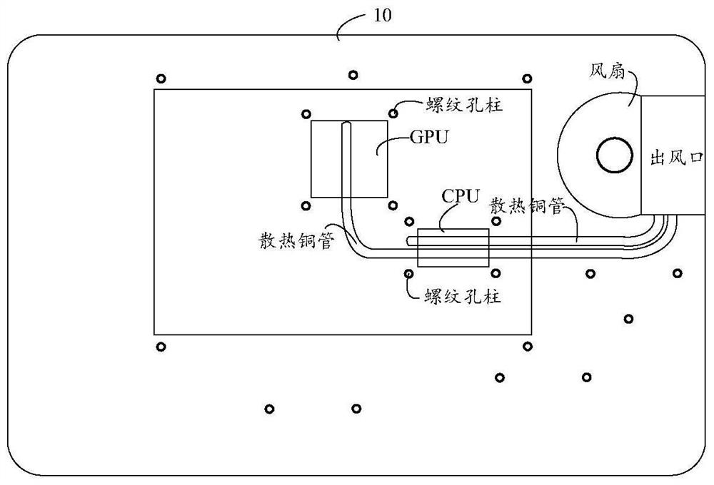
[0027] see figure 1 , figure 1 It is a brief schematic diagram of some parts and positions of the internal structure of the notebook computer 10 . Since this scheme only involves part of the structure, for the convenience of description, the introduction of the internal structure of the notebook is limited to the part involved in this scheme.

[0028] Notebook computer 10 can include CPU (Central Processing Unit, central processing unit) part, GPU (Graphics Processing Unit, graphics processing unit) part, and this is also the "big heat generator" when notebook computer 10 is running, therefore, computer hardware auxiliary cooling device 100 , the main thing that needs to be solved is the heat dissipation problem of the CPU part and the GPU part, so as to achieve a significant heat dissipation effe...


PUM


Abstract

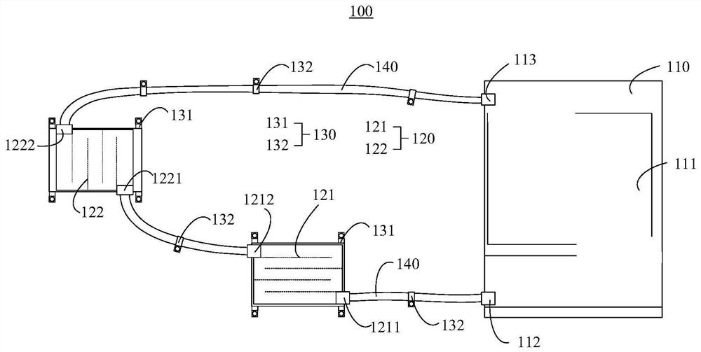
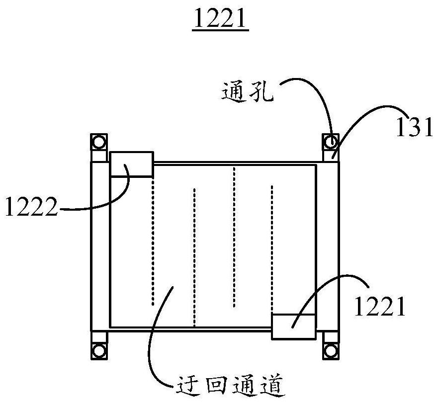
The invention provides an auxiliary heat dissipation device for computer hardware. The auxiliary heat dissipation device comprises a liquid cooling heat dissipation part, a liquid cooling pipeline, a copper cold head and an auxiliary fixing part. Relatively low-temperature cooling liquid is input into the copper cold head from the first liquid inlet through the heat dissipation liquid outlet of the liquid cooling heat dissipation part via the liquid cooling pipeline, so that the relatively low-temperature cooling liquid passes through a circuitous channel, takes away part of heat of a target part ( and becomes relatively high-temperature cooling liquid), flows out from the first liquid outlet, and returns to the heat dissipation structure of the liquid cooling heat dissipation part from the heat dissipation liquid inlet through the other section of liquid cooling pipeline for heat dissipation (and becomes cooling liquid with relatively low temperature). The circuitous channel communicating the first liquid inlet and the first liquid outlet in the copper cold head can prolong the time for the cooling liquid to flow through the copper cold head, so that more heat of a target part is taken away, and a better heat dissipation effect is achieved. Moreover, the air-cooled heat dissipation system of a notebook computer cannot be influenced, the air-cooled heat dissipation system can operate simultaneously, and the heat dissipation efficiency is ensured.

Description

technical field [0001] The present application relates to the field of computers, in particular, to a computer hardware-assisted cooling device. Background technique [0002] High temperature will not only lead to unstable operation of the computer system, shorten the service life, and may even burn some components. The function of the radiator is to absorb the heat and then dissipate it to ensure that the temperature of the computer components is normal. [0003] The current notebook computers usually still use air-cooled heat dissipation, which has low heat dissipation efficiency and is easy to absorb dust, making it difficult to clean the air inlet. Therefore, a notebook computer usually needs to rely on an external auxiliary cooling device. Conventional auxiliary heat dissipation devices for notebook computers either use brackets to elevate the notebook, so that the heat emitted by it can be fully dissipated to the external space (rather than on fixed parts, such as th...

Claims


Application Information

Patent Timeline
IPC IPC(8): G06F1/20G06F1/16
CPCG06F1/1616G06F1/20G06F2200/201
Inventor 刘旭健李俊蔡苏亚李丹王芳
Owner 陕西工业职业技术学院
Learn More