Light beam collimation module and illumination lamp

A technology for lighting lamps and collimating lens groups, which is applied to lighting devices, fixed lighting devices, lighting and heating equipment, etc., can solve the problems of thick lamps, poor spot cut-off, non-adjustable spot positions, etc., and achieve the effect of thin lamps and lanterns.

Active Publication Date: 2021-08-17
嘉兴追光智能科技有限公司
View PDF18 Cites 0 Cited by
  • Summary
  • Abstract
  • Description
  • Claims
  • Application Information

AI Technical Summary

Problems solved by technology

[0002] In recent years, there have been more and more artificial lighting fixtures on the market. Domestic and foreign companies have various related schemes, but they all have the following common defects: thicker lamps, poor light spot cut-off and non-adjustable spot position

Method used


Image

  • Light beam collimation module and illumination lamp
  • Light beam collimation module and illumination lamp
  • Light beam collimation module and illumination lamp

Examples


Embodiment 1

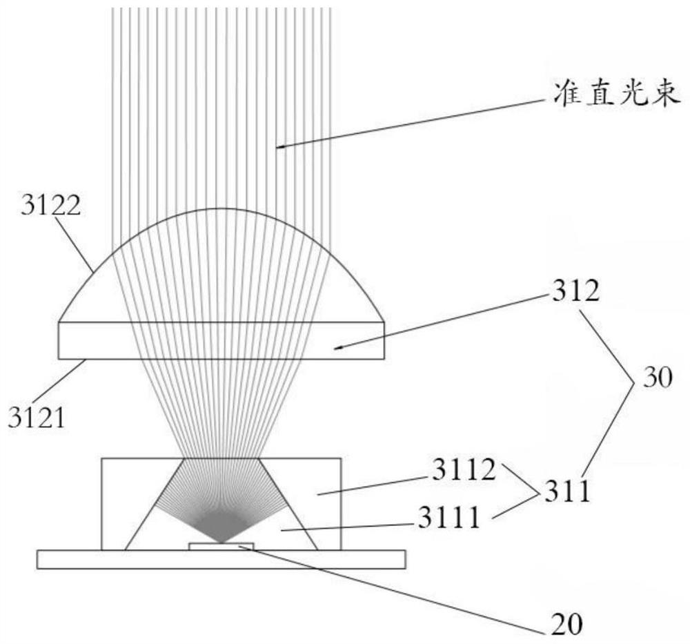
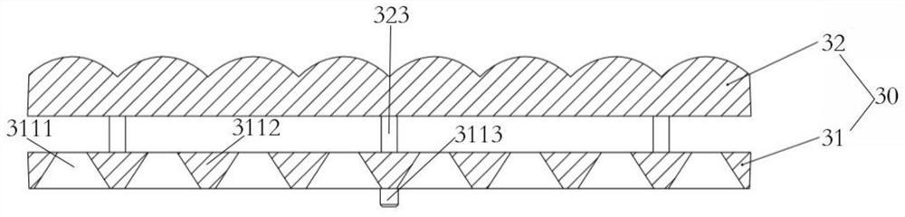
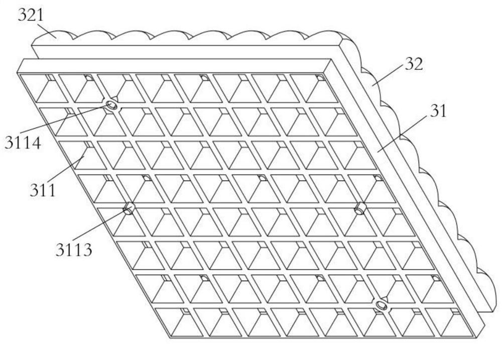
[0040] refer to Figure 1 to Figure 4 As shown, Embodiment 1 provides a beam collimation module 30 , including a cut-off grating group 31 and a collimating lens group 32 .

[0041] The light-cutting grating group 31 is constructed into a square structure, including a number of light-cutting grating units 311 arranged in an array, and each light-cutting grating unit 311 is composed of a light-transmitting part 3111 and a non-light-transmitting part 3112, the light-transmitting part The cross-sectional area of ​​3111 is a square or circular structure, and the cross-sectional area of ​​the light-transmitting part 3111 gradually decreases from the light-incoming side to the light-outgoing side of the light-cutting grating unit 311, and is located on the light-outgoing side of the light-cutting grating unit 31 A number of positioning holes are provided on the non-transparent part 3112 of the light-cutting grid group 31, and a number of limiting holes 3113 and limiting posts 3114 ar...

Embodiment 2

[0047] refer to Figure 5 to Figure 8 As shown, Embodiment 2 provides a lighting fixture, including a lamp base, a first light source group 20 , a beam collimating module 30 , a light guide plate 40 and a second light source group 50 .

[0048] The lamp base includes a backboard 11 and a housing 12 arranged around the backboard 11. The backboard 11 and the housing 12 form a receiving space with an opening on one side. The upper surface of the backboard 11 is fixed with a driving first light source group 20 and The driving module 60 for the second light source group 50 emits light. The upper surface of the back plate 11 is also provided with a hanger 70 .

[0049]The first light source group 20 is disposed in the containing space, and includes a plurality of first LED chips arrayed on the lower surface of the back plate 11 , and the first LED chips are white LED chips.

[0050] The beam collimating module 30 is arranged in the accommodation space, and includes a cut-off gratin...


PUM


Abstract

The invention discloses a light beam collimation module which comprises: a light intercepting grating set, wherein the light intercepting grating set comprises a plurality of light intercepting grating units arranged in an array mode, each light intercepting grating unit is composed of a light-transmitting part and a non-light-transmitting part, and the area of the cross section of the light transmitting part is gradually reduced from the light inlet side of the light intercepting grating unit to the light outlet side of the light intercepting grating unit; a collimating lens group which is configured on the light emitting side of the light intercepting grating set and comprises a plurality of collimating lens units arranged in an array mode, wherein each collimating lens unit corresponds to one light intercepting grating unit, and light beams condensed by the light intercepting grating units pass through the collimating lens units to form collimated parallel light beams to be emitted. The invention discloses an illumination lamp, which comprises the light beam collimation module and an RGB light guide module (a second light source group and a light guide plate), is used for simulating a real sky effect and a real solar facula effect, and can provide a comfortable illumination environment for human eyes.

Description

technical field [0001] The invention belongs to the technical field of lighting equipment, and in particular relates to a light beam collimation module and a lighting fixture. Background technique [0002] In recent years, the number of artificial lighting fixtures on the market has gradually increased. Domestic and foreign companies have various related solutions, but they all have the following common defects: thicker lamps, poor cut-off of the light spot, and non-adjustable spot position. [0003] Therefore, in view of the above technical problems, it is necessary to provide a light beam collimation module and a lighting fixture. Contents of the invention [0004] The purpose of the present invention is to provide a light beam collimation module and a lighting fixture for simulating the real sky effect and sun spot effect, so as to solve the problems in the prior art. [0005] In order to achieve the above object, the technical solution provided by an embodiment of the...

Claims


Application Information

Patent Timeline
Patent Type & Authority Applications(China)
IPC IPC(8): F21S8/00F21V5/04F21V13/02F21V19/00G02B27/30F21Y115/10
CPCF21S8/00F21V19/001F21V5/04F21V13/02G02B27/30F21Y2115/10Y02B20/40
Inventor 邓诗涛尹松
Owner 嘉兴追光智能科技有限公司
Why Eureka
Try Eureka