Light vertical multi-stage centrifugal pump

A centrifugal pump, vertical technology, applied in the field of light vertical multi-stage centrifugal pumps, can solve the problems of increasing energy loss, liquid cannot be sucked up, and cannot be formed large enough, so as to improve work efficiency, reduce energy loss, The effect of reducing friction

Active Publication Date: 2021-08-17
SHANGHAI RAYBON MACHINERY GRP
View PDF7 Cites 2 Cited by
  • Summary
  • Abstract
  • Description
  • Claims
  • Application Information

AI Technical Summary

Problems solved by technology

[0003] Existing multi-stage centrifugal pumps cannot be automatically adjusted according to changes in the liquid pressure inside the pump body. On the one hand, the working efficiency of the centrifugal pump is reduced and energy loss is increased; on the other hand, long-term use will frequently cause pump shaft fatigue, thereby Damage to the motor bearing; In addition, the existing centrifugal pump needs to be artificially filled with water and exhausted before use. If a sufficient vacuum cannot be formed in the shell, the liquid cannot be sucked up, that is, the phenomenon of air binding occurs. Therefore, in order to solve the above problem, we offer a lightweight vertical multistage centrifugal pump

Method used


Image

  • Light vertical multi-stage centrifugal pump
  • Light vertical multi-stage centrifugal pump
  • Light vertical multi-stage centrifugal pump

Examples


Embodiment Construction

[0030] The following will clearly and completely describe the technical solutions in the embodiments of the present invention with reference to the accompanying drawings in the embodiments of the present invention. Obviously, the described embodiments are only some, not all, embodiments of the present invention. Based on the embodiments of the present invention, all other embodiments obtained by persons of ordinary skill in the art without making creative efforts belong to the protection scope of the present invention.

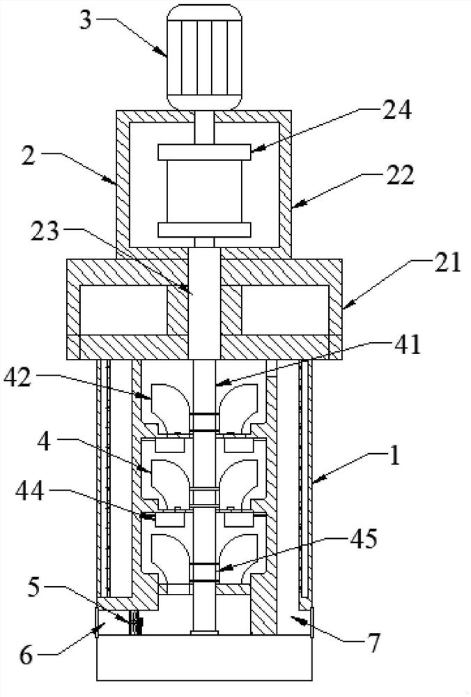
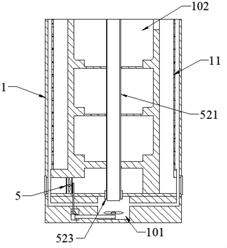
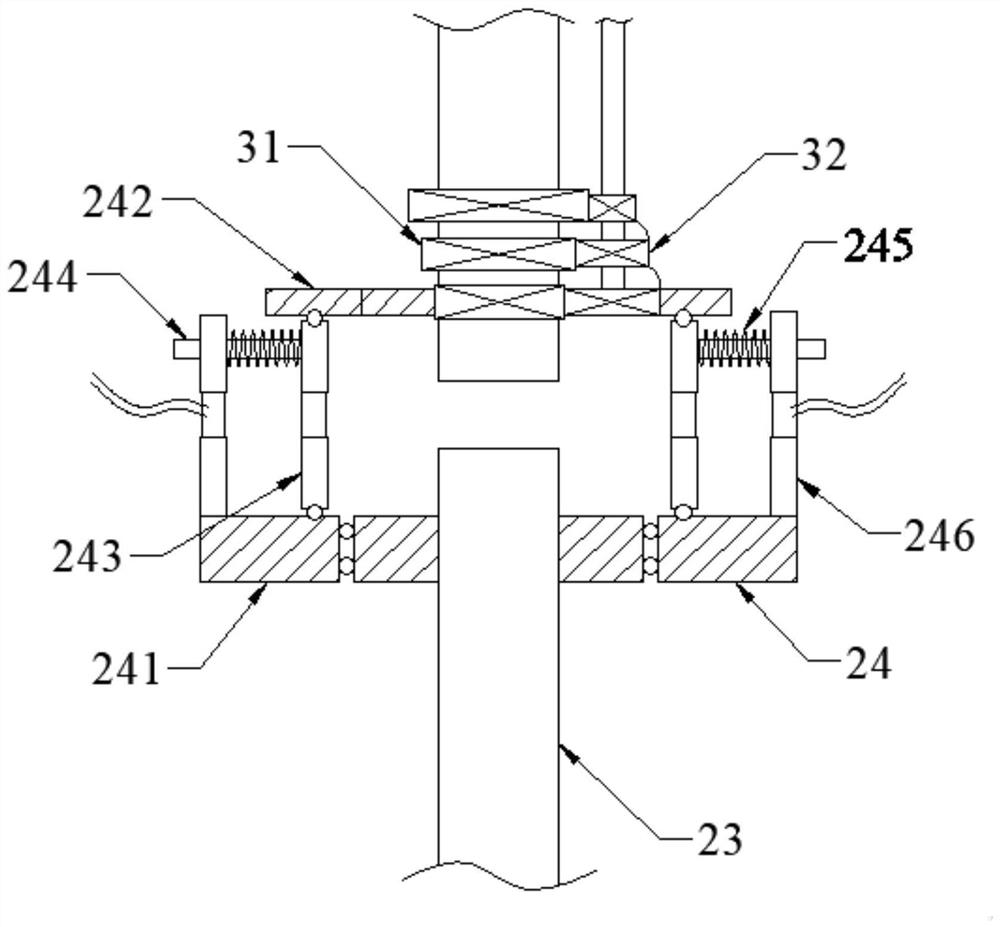
[0031] see Figure 1-7 , the present invention provides a technical solution: a light-duty vertical multistage centrifugal pump, including a pump body 1, a coupling mechanism 2, a motor 3, an operating mechanism 4 and an air extraction mechanism 5, and the pump body 1 is vertically arranged on On the working plane, the shaft coupling mechanism 2 is fixed directly above the pump body 1, the motor 3 is disposed on the top of the shaft coupling mechanism 2, and t...


PUM


Abstract

The invention discloses a light vertical multi-stage centrifugal pump which comprises a pump body, a coupling mechanism, a motor, an operation mechanism and an air exhaust mechanism, the pump body is arranged on a working plane in the vertical direction, the coupling mechanism is fixedly arranged over the pump body, the motor is arranged at the top end of the coupling mechanism, and the output end of the motor penetrates through and extends into the coupling mechanism. One end of the operation mechanism is connected with the coupling mechanism, and the other end of the operation mechanism penetrates through and extends into the pump body. A water outlet pipeline and a water inlet pipeline are symmetrically arranged in the pump body with respect to the central axis, one end of the water outlet pipeline and one end of the water inlet pipeline communicate with a water pipe and provided with valves, and the other end of the water outlet pipeline and the other end of the water inlet pipeline communicate with the operation mechanism. An existing multi-stage centrifugal pump cannot be automatically adjusted according to changes of liquid pressure in a pump body, on one hand, the working efficiency of the centrifugal pump is reduced, and energy loss is increased; and on the other hand, pump shaft fatigue can be caused frequently after long-term use, and a motor bearing is damaged.

Description

technical field [0001] The invention relates to the technical field of centrifugal pumps, in particular to a light vertical multistage centrifugal pump. Background technique [0002] A multi-stage centrifugal pump refers to the collection of two or more centrifugal pumps with the same function. Specifically, the pressure relief port of the first stage communicates with the inlet of the second stage, and the pressure relief port of the second stage communicates with the inlet of the third stage. The inlets are connected, and so on, in series to form a multi-stage centrifugal pump. Multistage centrifugal pumps are mostly suitable for water supply, industrial pressurization, industrial liquid transportation, water treatment, irrigation and other occasions. They have the characteristics of compact structure, small size and light weight. [0003] Existing multi-stage centrifugal pumps cannot be automatically adjusted according to changes in the liquid pressure inside the pump bo...

Claims


Application Information

Patent Timeline
Patent Type & Authority Applications(China)
IPC IPC(8): F04D1/06F04D13/06F04D13/02F04D29/00F04D29/04F04D29/06F04D15/00F04D25/04F03B13/00
CPCF04D1/06F04D13/06F04D13/02F04D29/007F04D29/04F04D29/061F04D15/0066F04D15/0005F04D25/04F03B13/00
Inventor 蒋必瑞
Owner SHANGHAI RAYBON MACHINERY GRP
Why Eureka
Try Eureka