
Thermal image tracking and control method for high-temperature smelting soft stirring system

A technology of high-temperature smelting and control methods, which can be used in closed-circuit television systems, components of television systems, image enhancement, etc., and can solve problems such as inaccurate gas flow control

Pending Publication Date: 2021-08-13
宁心怡
View PDF2 Cites 2 Cited by
  • Summary
  • Abstract
  • Description
  • Claims
  • Application Information

AI Technical Summary

Problems solved by technology

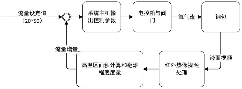
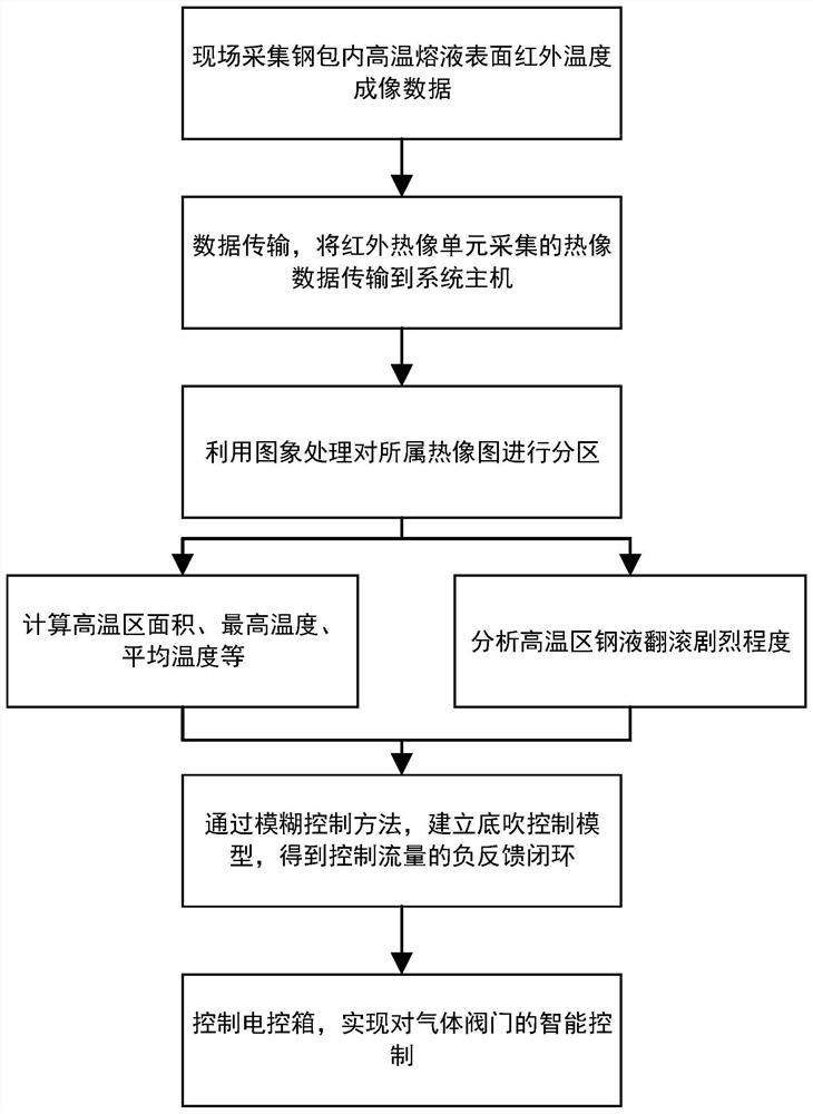
[0004] The purpose of the present invention is to provide a thermal image tracking and control method for a high-temperature smelting soft stirring system, aiming to solve the problem of inaccurate gas flow control in ladle bottom blowing in the prior art

Method used


Image

  • Thermal image tracking and control method for high-temperature smelting soft stirring system
  • Thermal image tracking and control method for high-temperature smelting soft stirring system

Examples


Embodiment Construction

[0022] In order to make the object, technical solution and advantages of the present invention clearer, the present invention will be further described in detail below in conjunction with the accompanying drawings and embodiments. It should be understood that the specific embodiments described here are only used to explain the present invention, not to limit the present invention.

[0023] In the drawings of this embodiment, the same or similar symbols correspond to the same or similar components; The indicated orientation or positional relationship is based on the orientation or positional relationship shown in the drawings, and is only for the convenience of describing the present invention and simplifying the description, rather than indicating or implying that the referred device or element must have a specific orientation, or in a specific orientation. Construction and operation, so the words describing the positional relationship in the drawings are only for illustrative...


PUM


Abstract

The invention relates to the technical field of steelmaking in the metallurgical industry, and discloses a thermal image tracking and control method for a high-temperature smelting soft stirring system. The method includes: firstly, collecting thermal image data of the liquid level in the steel ladle through the high-temperature infrared thermal image unit, and transmitting the data to the system host; then, automatically detecting an image and temperature distribution formed on the surface of the molten steel by bottom blowing, and partitioning the thermogram by image processing; calculating the area, the highest temperature, the average temperature and the like of a high-temperature region of the molten steel according to the partitions, analyzing the rolling intensity of the molten steel in the high-temperature region, and establishing a corresponding relation between the input image and the output bottom blowing pipeline gas flow; establishing a bottom blowing control model through a fuzzy control method, obtaining a negative feedback closed loop for controlling flow, and calculating and outputting a reasonable target flow value; and finally, enabling the electric cabinet to controls a gas valve of the steel ladle bottom blowing pipeline according to the target flow value, so that the gas flow of the steel ladle bottom blowing pipeline is controlled. According to the invention, intelligent control of ladle bottom blowing is realized.

Description

technical field [0001] The invention relates to the technical field of ladle bottom blowing, in particular to a thermal image tracking and control method of a high-temperature smelting soft stirring system. Background technique [0002] In the converter steelmaking process in the metallurgical industry, after the converter smelting is completed, the molten steel needs to be poured into the ladle for bottom blowing argon stirring. Although this process is short, it plays a non-negligible role in the quality assurance of the subsequent molten steel products. Steel ladle is also called steel ladle, which is mainly used in steelmaking plants and foundries to undertake molten steel and perform pouring operations before open hearth furnaces, electric furnaces or converters. With the rapid development of out-of-furnace refining, especially the wide application of various refining furnaces, the role of the ladle has attracted more and more attention; during high-temperature smelting...

Claims


Application Information

Patent Timeline
Patent Type & Authority Applications(China)
IPC IPC(8): G06K9/62G06T5/30G06T5/40G06T7/11G06T7/136G06T7/155H04N5/33H04N7/18C21C7/00
CPCG06T7/11G06T7/136G06T7/155G06T5/30G06T5/40H04N5/33H04N7/18C21C7/00G06T2207/10048G06T2207/20081G06T2207/30136G06F18/2411
Inventor 宁心怡
Owner 宁心怡
Learn More