Camera module with heating device
A technology for heating devices and camera modules, which is applied to coil devices, induction heating, camera bodies, etc., can solve the problems that camera modules do not have heating functions, and achieve low energy transfer efficiency, short heating time, and shortened use The effect of longevity
- Summary
- Abstract
- Description
- Claims
- Application Information
AI Technical Summary
Problems solved by technology
Method used
Image

Examples
no. 1 example
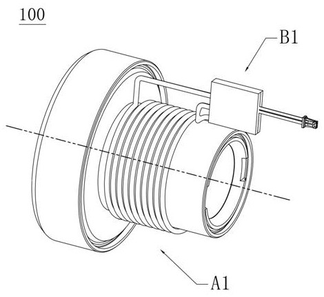
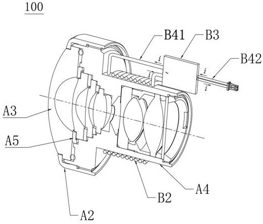
[0042] see Figure 2 to Figure 4 , the camera module 100 with a heating device provided in the first embodiment of the present invention includes: a camera lens assembly A1, and a heating device B1 for heating the camera lens assembly A1. Wherein, the camera lens assembly A1 at least includes a pressure ring A2, a lens group A3, a lens barrel A4, a spacer A5, and a lens holder (not shown in the figure). The heating device B1 includes a coil B2, an inverter B3, a first wire B41 for connecting the coil B2 and the inverter B3, and a second wire B42 for connecting the inverter B3 and the system power supply.
[0043] Among them, the lens group A3 is installed in the lens barrel A4 for optical imaging; the pressure ring A2 is used to lock the lens group A3 to the lens barrel A4; the spacer ring A5 is used for mutual support between the lenses in the lens group A3; The lens barrel A4 is used for abutment and position limitation among components such as the pressure ring A2, the len...
no. 2 example
[0056] see Figure 5 to Figure 7 The camera module 200 with a heating device provided in the second embodiment of the present invention includes: a camera lens assembly A1, and a heating device B1 for heating the camera lens assembly A1. Wherein, the camera lens assembly A1 at least includes a pressure ring A2, a lens A3, a lens barrel A4, a spacer A5, and a lens holder (not shown in the figure). The heating device B1 includes a coil B2, an inverter B3, a first wire B41 for connecting the coil B2 and the inverter B3, and a second wire B42 for connecting the inverter B3 and the system power supply.
[0057] Among them, the lens group A3 is installed in the lens barrel A4 for optical imaging; the pressure ring A2 is used to lock the lens group A3 to the lens barrel A4; the spacer ring A5 is used for mutual support between the lenses in the lens group A3; The lens barrel A4 is used for abutment and position limitation among components such as the pressure ring A2, the lens group...
no. 3 example
[0071] see Figure 8 to Figure 10 The camera module 300 with a heating device provided in the third embodiment of the present invention includes: a camera lens assembly A1, and a heating device B1 for heating the camera lens assembly A1. Wherein, the camera lens assembly A1 at least includes a pressure ring A2, a lens A3, a lens barrel A4, a spacer A5, and a lens holder (not shown in the figure). The heating device B1 includes a coil B2, an inverter B3, a first wire B41 for connecting the coil B2 and the inverter B3, and a second wire B42 for connecting the inverter B3 and the system power supply.
[0072] Among them, the lens group A3 is installed in the lens barrel A4 for optical imaging; the pressure ring A2 is used to lock the lens group A3 to the lens barrel A4; the spacer ring A5 is used for mutual support between the lenses in the lens group A3; The lens barrel A4 is used for abutment and position limitation among components such as the pressure ring A2, the lens group...
PUM
 Abstract
Description
Claims
Application Information
 - Generate Ideas
- Intellectual Property
- Life Sciences
- Materials
- Tech Scout
- Unparalleled Data Quality
- Higher Quality Content
- 60% Fewer Hallucinations
Browse by: Latest US Patents, China's latest patents, Technical Efficacy Thesaurus, Application Domain, Technology Topic, Popular Technical Reports.
© 2025 PatSnap. All rights reserved.Legal|Privacy policy|Modern Slavery Act Transparency Statement|Sitemap|About US| Contact US: help@patsnap.com