
Calculation method of diode junction capacitance

A calculation method, diode junction technology, applied in capacitance measurement, measurement of electrical variables, measurement of resistance/reactance/impedance, etc., can solve problems such as complex calculation methods, achieve the effect of reducing complexity and having universal applicability

Pending Publication Date: 2021-08-13
SHENZHEN GRADUATE SCHOOL TSINGHUA UNIV
View PDF0 Cites 1 Cited by
  • Summary
  • Abstract
  • Description
  • Claims
  • Application Information

AI Technical Summary

Problems solved by technology

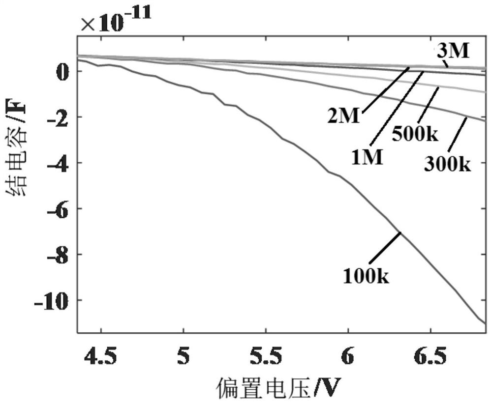
[0013] In view of this, the present invention proposes a calculation method for diode junction capacitance, which replaces ω with a measurable physical quantity, so that the junction capacitance value of a diode at any frequency can be calculated regardless of the size relationship between G and ωC, and solves the current problem The calculation method of diode junction capacitance needs to meet the preconditions and if the preconditions are not met, the calculation method is very complicated.

Method used


Image

  • Calculation method of diode junction capacitance
  • Calculation method of diode junction capacitance
  • Calculation method of diode junction capacitance

Examples


Embodiment Construction

[0027] The present invention will be further described below in conjunction with the accompanying drawings and specific embodiments.

[0028] A specific embodiment of the present invention proposes a method for calculating diode junction capacitance, including the following steps A1-A7:

[0029] A1. Under the preset modulation frequency and preset bias voltage V, measure the apparent capacitance value C of the diode p , apparent conductance value G p , the real part R of the S11 parameter S11 and imaginary part X S11 and the voltage-current data pair V-I.

[0030] Wherein, the preset modulation frequency can be in the range of 0-5MHz, and does not include 0; the preset bias voltage is in the range of 0-V max In the range of volts, and does not include 0; where V max Indicates the maximum DC voltage that the diode can withstand. The S11 parameter is one of the S parameters, which represents the return loss characteristic. Generally, the dB value and impedance characterist...


PUM


Abstract

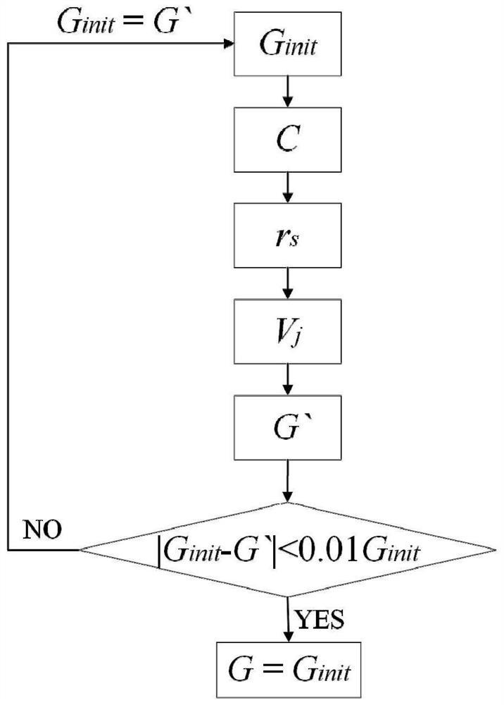
The invention discloses a diode junction capacitance calculation method. The method comprises the following steps: A1, measuring an apparent capacitance value, an apparent conductivity value, an S11 parameter real part, an S11 parameter imaginary part and voltage-current of a diode; A2, calculating a real part and an imaginary part of diode impedance by using the real part and the imaginary part of the parameter S11; A3, according to the impedance relation between the two equivalent circuits of the diode, obtaining calculation formulas of junction capacitance and series resistance; A4, setting an initial junction conductance value Ginit; A5, substituting the initial junction conductance value into the junction capacitance calculation formula to obtain a current junction capacitance value; A6, substituting the current junction capacitance value and the initial junction conductance value into the series resistance calculation formula to obtain a current series resistance value, obtaining a voltage applied to the junction conductance or the junction capacitor according to a voltage-current relationship, and obtaining a current junction conductance calculation value G' according to a conductance formula; and A7, judging whether the difference value between the Ginit and the G' is smaller than a preset threshold value or not; if so, taking the current junction capacitance value as the final value of the junction capacitance; and if not, making Ginit to be equal to G', and executing the step A5 again.

Description

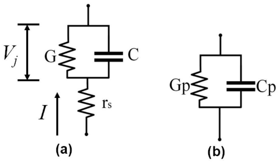
technical field [0001] The invention relates to the technical field of electronic components, in particular to the technical field of semiconductor devices, and in particular to a method for calculating diode junction capacitance. Background technique [0002] Usually the diode can be equivalent to figure 1 The equivalent circuit shown in (a) is composed of junction capacitance C, junction conductance G and series resistance r s composition. In a diode capacitance measurement setup, the figure 1 (b) The parallel equivalent circuit shown, that is, the diode is equivalent to parallel apparent conductance Gp and apparent capacitance Cp. Usually the idea of ​​calculating capacitance is as follows: [0003] because figure 1 (a) with figure 1 (b) The circuit is also a diode equivalent circuit, so the impedance of the two circuits is equal, that is: [0004] [0005] [0006] Among them, ω represents the frequency of the alternating current applied to the diode during ...

Claims


Application Information

Patent Timeline
IPC IPC(8): G01R27/26
CPCG01R27/2605
Inventor 董宇涵马克铭张石曹智渊
Owner SHENZHEN GRADUATE SCHOOL TSINGHUA UNIV
Learn More