Intelligent injection mold for sealing part
A technology for injection molds and seals, which is applied in the field of intelligent injection molds for seals, can solve problems such as the detection of airtightness of seals, and achieve the effects of improving flatness, improving draft efficiency, and improving draft effect
- Summary
- Abstract
- Description
- Claims
- Application Information
AI Technical Summary
Problems solved by technology
Method used
Image

Examples
Embodiment 1
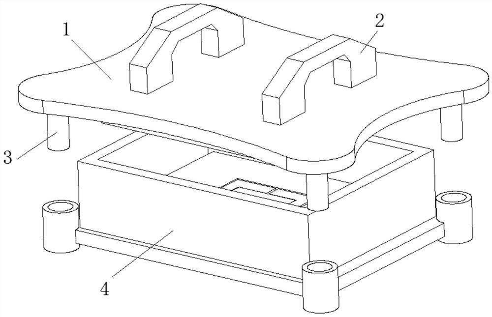
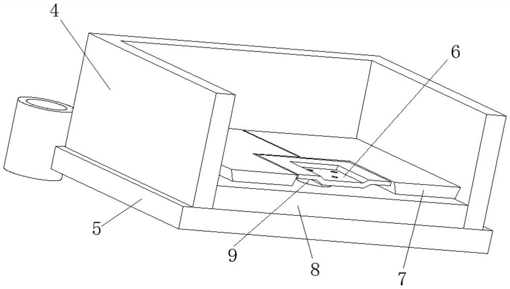
[0034] like Figure 1-4 As shown, the present invention provides a technical solution: a seal intelligent injection mold comprising a press top plate 1, and the upper surface of the pressure die top plate 1 is fixedly connected to a fixed handle 2, the pressure die top plate 1 surface The side surface is fixed at the side side, and the outer surface cover of the transmission shaft 3 is provided with a mold base 5, and the upper surface of the mold base 5 is fixedly connected to a compression mold housing 4, the mid-surface base 5 upper surface. The collecting plate 8 is fixed at a fixed connection, and the first inlet air hole 9 is provided at the surface of the collecting plate 8, and the first inlet air hole 9 is provided with an open template device 6, and the outer surface cover of the opening template device 6 is provided. It is provided with anti-slit device 7;
[0035] The open template device 6 includes a triangular plastic block 65 that is fixedly coupled with an open die ...
Embodiment 2
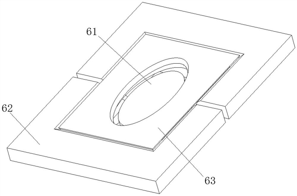
[0041] like Figure 5 As shown, in the basis of the first example, the present invention provides a technical solution: the shear device 61 includes a ring cutter 612 and a shear plate 611, and the bottom fixed connection of the annular cutter 612 has a ring plastic sleeve. 615, the annular surface of the annular plastic sleeve 615 is fixedly coupled with a plastic separation block 614.
[0042] The outer surface of the shear plate 611 is fixedly coupled with a leakage loop 616, and a second groove 613 is opened at the top of the outer surface of the leakage loop 616, and the outer surface of the leak plate 616 is fixedly connected. The side of the plastic block 614 is located. Through the annular cutter 612 cutting the material leaking under the mold, the ring cutter 612 can be resected at the bottom of the internal mold material, and improve the flatness of the outer surface of the injection mold.
[0043] The second embodiment has the following steps:
[0044] The annular cutter...
Embodiment 3
[0046] like Figure 6-7 As shown, in the basis of the first and embodiment 2, the present invention provides a technical solution: the anti-slitting device 7 includes a compression backplane 71, and the outer surface of the compression bottom plate 71 is sleeved in a compression shell 4. Internally, a sealing groove 76 is opened at the surface of the compression bottom plate 71, and the intermediate position thread at the recess in the sealing groove 76 has a rotary block device 72.
[0047] The top portion of the rotating block device 72 is fixedly coupled with a sewing plate 73, and the upper surface of the sewing plate 73 is fixedly coupled with curved plates 74, and the curved plate 74 is fixed from one side of the sewing plate 73 fixedly connected to the rotary rod plate. 77. The opposite surface of the rotary rod plate 77 is fixedly connected to the elastic shaft 75. By the easily bending characteristics of the bending plate 74 during the pressure mold, the compression bottom...
PUM
 Abstract
Description
Claims
Application Information
 - R&D
- Intellectual Property
- Life Sciences
- Materials
- Tech Scout
- Unparalleled Data Quality
- Higher Quality Content
- 60% Fewer Hallucinations
Browse by: Latest US Patents, China's latest patents, Technical Efficacy Thesaurus, Application Domain, Technology Topic, Popular Technical Reports.
© 2025 PatSnap. All rights reserved.Legal|Privacy policy|Modern Slavery Act Transparency Statement|Sitemap|About US| Contact US: help@patsnap.com