Lamp holder reflective bowl assembling device and assembling method

A technology for assembling device and reflective bowl, which is applied in assembly machines, metal processing equipment, manufacturing tools, etc., can solve the problems of easily damaged reflective bowl structure, high scrap rate of finished products, difficult to promote and use, etc., so as to avoid deformation and scrap, assembly quality Stable and ensure the effect of assembly quality

Active Publication Date: 2021-08-13
HUAIYIN INSTITUTE OF TECHNOLOGY
View PDF6 Cites 1 Cited by
  • Summary
  • Abstract
  • Description
  • Claims
  • Application Information

AI Technical Summary

Problems solved by technology

Although the assembly equipment in this application can replace manual assembly and improve the assembly efficiency, the equipment uses the pressure head to press down to realize the bending of the folded edge, which is unreliable. The folded edge is initially in a vertical upward state, and the wear Through the square hole on the lamp holder, the two folded edges need to be pressed against each other to ensure a firm assembly. It is difficult to ensure that each bend of the folded edge meets the requirements by pressing down the pressure head. Assembly will cause the reflective bowl to be subjected to too much downward pressure, which will easily damage the structure of the reflective bowl. Using this equipment for assembly will lead to a high scrap rate of finished products, making it difficult to popularize and use

Method used


Image

  • Lamp holder reflective bowl assembling device and assembling method
  • Lamp holder reflective bowl assembling device and assembling method
  • Lamp holder reflective bowl assembling device and assembling method

Examples


Embodiment 1

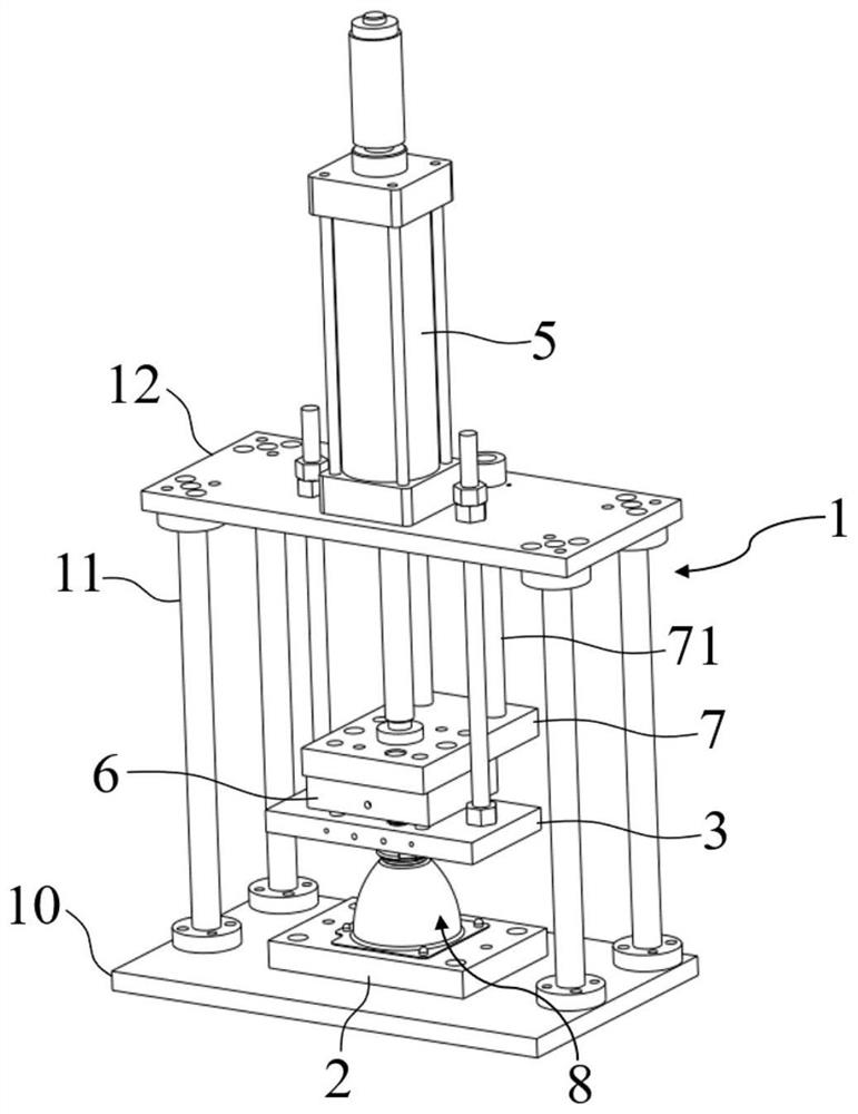
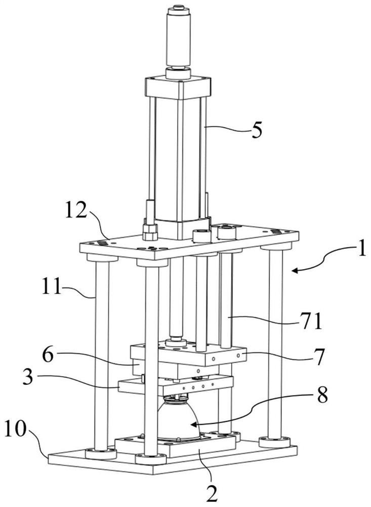
[0068] The lamp holder reflective bowl assembly device of this embodiment includes:

[0069] pedestal 1;

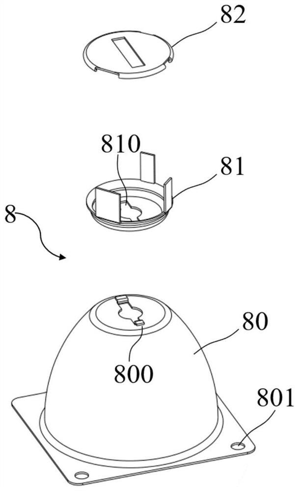
[0070] The mounting plate 2 is placed horizontally on the bottom of the base frame 1, and the lamp housing 8 to be assembled is placed on the mounting plate 2;

[0071] The fixed plate 3 is horizontally fixed above the mounting plate 2;

[0072] Assembly mechanism 4, which includes two rotary claws with the same shape and arranged symmetrically to each other. The rotary claws include an inclined part 40, a positioning part 41 and a working part 42 from top to bottom. A waist-shaped hole 400 is penetrated on the inclined part 40, and the length direction of the waist-shaped hole 400 is along the length direction of the inclined part 40. A fixing hole 410 is penetrated on the positioning part 41, and the surfaces of the two working parts 42 facing away from each other are formed by depressions. With card slot 420,

[0073] Assembly mechanism 4 also comprises pin one 43 a...

Embodiment 2

[0080] The reflective bowl assembly device of the lamp holder in this embodiment is further improved on the basis of Embodiment 1, and the base frame 1 includes:

[0081] base plate 10, which is arranged horizontally;

[0082] Upright column 11, it has several, vertical arrangement, one end of upright column 11 is fixedly connected with bottom plate 10 top surface;

[0083] The horizontal plate 12 is arranged horizontally and fixed on the other end of the column 11;

[0084] The driving mechanism 5 is a cylinder, which is fixed on the horizontal plate 12, and the telescopic rod 50 of the cylinder stretches out from the bottom of the horizontal plate 12;

[0085] The mounting plate 2 is fixed on the top surface of the base plate 10 , and the top surface of the mounting plate 2 protrudes upwards to form a mounting pile 20 . The shape and position of the mounting pile 20 matches the shape and position of the lamp mounting hole 801 .

[0086] Such as Figure 4 with Figure 5 A...

Embodiment 3

[0088] The reflective bowl assembly device for the lamp base of this embodiment is further improved on the basis of Embodiments 1 and 2. The top surface of the installation plate 2 is provided with a support column 21, and the bottom surface of the support column 21 is detachable from the top surface of the installation plate 2. Connected, the top surface of the support column 21 abuts against the rear end of the inner wall of the reflective bowl 80 .

[0089] Such as Figure 4 with Figure 5 As shown, the main function of the support column 21 is to be arranged inside the reflective bowl 80 during assembly. The bottom of the support column 21 is in contact with the mounting plate 2, and the top is in contact with the tail end of the inner wall of the reflective bowl 80. When assembling, pass The support column 21 supports the reflective bowl 80, which can ensure that the reflective bowl 80 will not be subjected to downward pressure, and avoid the situation that the reflectiv...


PUM


Abstract

The invention discloses a lamp holder reflective bowl assembling device and method, and belongs to the field of automobile part machining. The lamp holder reflective bowl assembling device comprises a base frame, a mounting plate, a fixed plate, and an assembling mechanism, wherein the mounting plate is horizontally arranged at the bottom of the base frame; the fixed plate is horizontally fixed above the mounting plate; the assembling mechanism comprises two rotating claws which are the same in shape and are symmetrically arranged; each rotating claw sequentially comprises an inclined part, a positioning part and a working part from top to bottom; the assembling mechanism further comprises a first pin shaft and two second pin shafts; the first pin shaft sequentially penetrates through kidney-shaped holes in the inclined parts of the two rotating claws; the number of the second pin shafts is two; the two second pin shafts penetrate through fixing holes in the positioning parts of the two rotating claws respectively and are rotationally connected with the fixed plate; and the lamp holder reflective bowl assembling device further comprises a driving mechanism, wherein the driving mechanism is used for providing vertically downward driving force for the first pin shaft. According to the lamp holder reflective bowl assembling device and method, downward driving force is applied through the driving mechanism, so that the two rotating claws of the assembling mechanism rotate to bend the two folded edges of the reflective bowl in a back-to-back mode to complete assembling of an automobile lamp shell; and the lamp holder reflective bowl assembling device is simple in structure, low in cost, high in assembling efficiency and stable in assembling quality.

Description

technical field [0001] The invention belongs to the field of auto parts processing, and more specifically relates to an assembly device and an assembly method for a reflective bowl of a lamp holder. Background technique [0002] The reflective bowl is an important part of the car light, which is used to gather and reflect the light source of the car light, and plays an important role in driving at night. [0003] Existing lamp housing structure such as figure 1 As shown, the flange around the head end of the reflective bowl is provided with a lamp installation hole, and the rear end of the reflective bowl is provided with a square hole. The protruding bendable edge is connected with the lamp holder, and there is only this connection between the reflective bowl and the lamp holder. All have square holes. [0004] The assembly of the reflective bowl of the existing lamp holder is usually manual assembly. The operator uses tools to pass through the square hole of the lamp co...

Claims


Application Information

Patent Timeline
Patent Type & Authority Applications(China)
IPC IPC(8): B23P21/00
CPCB23P21/00
Inventor 李年莲刘宬邑董育伟曹博文张益民刘林海
Owner HUAIYIN INSTITUTE OF TECHNOLOGY
Why Eureka
Try Eureka