Small base station communication equipment antenna supporting and clamping device and method thereof

A technology for communication equipment and antenna support, which is applied in the direction of antenna supports/installation devices, antennas, antenna parts, etc., can solve the problems of unstable connection between base station antennas and poles, inflexible adjustment angles, etc., so that it is not easy to slip, good Flexibility, the effect of increasing friction

Inactive Publication Date: 2021-08-10
单海建
View PDF0 Cites 9 Cited by
  • Summary
  • Abstract
  • Description
  • Claims
  • Application Information

AI Technical Summary

Problems solved by technology

[0006] The purpose of the present invention is to provide a small base station communication equipment antenna supporting and clamping device and its method, which can solve the problems of unstable connection between base station antenna and pole and inflexible adjustment angle

Method used


Image

  • Small base station communication equipment antenna supporting and clamping device and method thereof
  • Small base station communication equipment antenna supporting and clamping device and method thereof
  • Small base station communication equipment antenna supporting and clamping device and method thereof

Examples


Embodiment 1

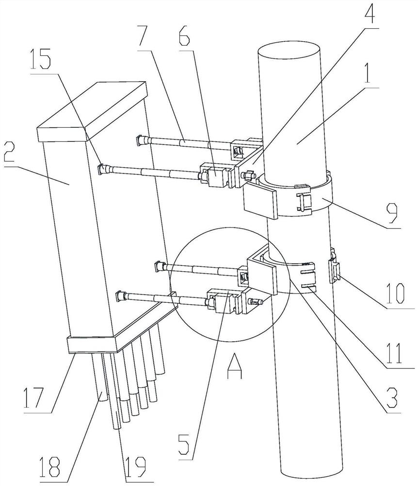
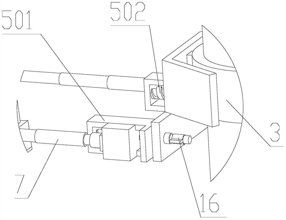
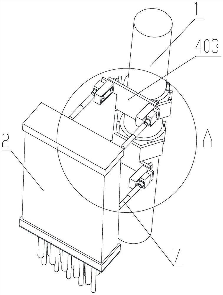
[0043] see Figure 1 to Figure 8 The technical solution provided by the present invention is a small base station communication equipment antenna support and clamping device, including a clamp mechanism connecting the pole 1 and the base station antenna 2 and an adjustment mechanism arranged on one side of the clamp mechanism. The clamp mechanism includes Two upper and lower ring-shaped clamps 3 sleeved on the pole 1 and two connecting plates 4 arranged on one side of the clamping hoop 3, the adjustment mechanism includes slide rails 5 arranged at both ends of the connecting plate 4 close to the base station antenna 2 , the slider 6 that is slidingly connected to the inside of the slide rail 5 and the telescopic rod 7 that is ball-hingedly connected to one side of the slider 6 and one side of the base station antenna 2; the clamp mechanism can firmly clamp the device on the pole 1, and Two upper and lower clamps 3 are set to realize double fixation of the device; the connectin...

Embodiment 2

[0062] see Figure 9 , On the basis of Embodiment 1, the difference from Embodiment 1 is that the isolation rod 18 is a triangular rod, and the isolation rod 18 is made of insulating rubber. The triangular structure can better block two adjacent connecting wires and prevent them from being entangled; the triangular rod allows several isolation surfaces to exist between every two connecting wires 19, and the isolation effect is better.

[0063] The working principle of the present invention: After the worker arrives at the position where the base station antenna 2 needs to be installed, he first pulls the handle 10 to rotate the inner ring 9, and the opening on the inner ring 9 corresponds to the opening on the clamp 3, and the handle 10 is stuck in the In the handle slot 11, align the opening with the pole 1, clamp the clamp 3 on the pole 1 with force, the clamp 3 and the rotating inner ring 9 can be made of elastic material; then pull the handle 10 again to rotate the rotatin...


PUM


Abstract

The invention provides a small base station communication equipment antenna supporting and clamping device and a method thereof, belongs to the technical field of antenna supporting and clamping equipment, and aims to solve the problems of unstable connection between the base station antenna and the vertical rod and inflexible angle adjustment. According to the technical scheme, the device comprises a hoop mechanism for connecting a vertical rod and a base station antenna and an adjusting mechanism arranged on one side of the hoop mechanism, wherein the hoop mechanism comprises two hoops and two connecting plates, and the two hoops are connected to the vertical rod in a sleeving mode. The small base station communication equipment antenna supporting and clamping device and method have the beneficial effects that the telescopic rod is in spherical hinge connection with the sliding block and the spherical hinge base on the base station antenna, a worker rotates the base station antenna with hands to adjust a base station to keep an optimal inclination angle so as to keep an optimal communication signal, and spherical hinge connection has good flexibility, so that angle adjustment can be carried out in the vertical direction and the horizontal direction.

Description

technical field [0001] The present invention relates to the technical field of antenna support and clamping equipment, in particular to an antenna support and clamping device and method for small base station communication equipment. Background technique [0002] At this stage, the construction of communication networks continues to speed up, and small base stations are used more and more in people's lives. Antennas are components used to receive wireless signals and are indispensable in small base station communication equipment. [0003] The antenna is easy to shake when encountering severe weather such as thunderstorms and strong winds. The main function of the supporting and clamping mechanism is to clamp and fix the antenna to ensure that the antenna is more stable when working. At present, the connecting rods are usually hinged at the upper and lower ends of one side of the antenna. In order to facilitate angle adjustment, some connect two hinged connecting rods at the...

Claims


Application Information

Patent Timeline
Patent Type & Authority Applications(China)
IPC IPC(8): H01Q1/24H01Q3/02
CPCH01Q1/246H01Q3/02
Inventor 单海建
Owner 单海建
Why Eureka
Try Eureka