Improved structure of drum brake

A drum brake, a pair of technology, applied in the field of motorcycle and electric vehicle brake devices, can solve the problems of large vehicle braking sliding distance, easy wear of the brake cam, poor braking effect of drum brakes, etc.

Pending Publication Date: 2021-08-10
申革英
View PDF0 Cites 0 Cited by
  • Summary
  • Abstract
  • Description
  • Claims
  • Application Information

AI Technical Summary

Problems solved by technology

[0003] The purpose of the present invention is to provide an improved structure of the drum brake, which changes the working mode of the original drum brake which uses the cam to directly drive the expansion of the brake shoe, and effectively improves the poor braking effect of the existing drum brake, the large sliding distance of the vehicle brake, and the large braking distance of the brake cam. Disadvantages of wear and tear

Method used


Image

  • Improved structure of drum brake
  • Improved structure of drum brake

Examples


Embodiment

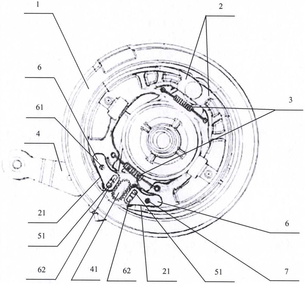
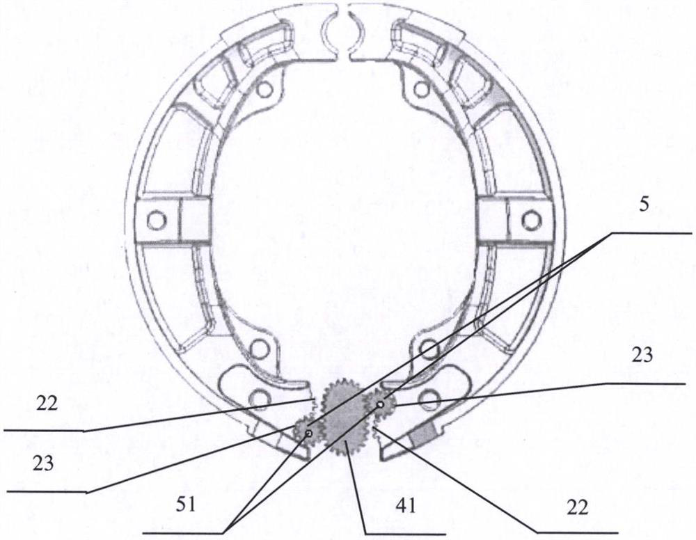
[0007] as attached figure 1 , attached figure 2 As shown, a pair of brake shoes (2) are installed in the casing (1), the elastic reset element (3) is connected between the brake shoes (2), and one end of the pair of brake shoes (2) is rotatably positioned on the casing In (1), a waist-shaped columnar brake gear (41) driven by the brake rocker arm assembly (4) is provided between the end gaps at the other end, and the waist-shaped columnar brake gear (41) is connected to the brake shoes (2) on both sides. ) between the end faces of a roller gear (5), the rivet (7) fixes the connecting piece (6) in the pit (21) of a pair of brake shoes (2), and the roller gear (5) The shaft (51) is installed in the waist-shaped hole (62) of the connecting piece (6) and can rotate and move therein. When the brake rocker arm assembly (4) drives the waist-shaped columnar brake gear (41) to rotate, the waist-shaped columnar brake wheel (41) drives the two roller gears (5) to rotate and move, and ...


PUM


Abstract

The invention provides an improved structure of a drum brake. A pair of brake shoes are installed in a drum brake shell, one end of each brake shoe is rotationally positioned in the shell, and a kidney-shaped columnar brake gear driven by a brake rocker arm assembly to rotate is arranged in an end gap of the other ends of the brake shoes; Pin roller gears are meshed between the kidney-shaped columnar brake gear and the end faces of the brake shoes on the two sides; and rotating shafts of the pin roller gears are installed in kidney-shaped holes of connecting pieces and can rotate and move in the kidney-shaped holes, and the connecting pieces are riveted and fixed to the pair of brake shoes through rivets. When the brake rocker arm assembly drives the kidney-shaped columnar brake gear to rotate, the kidney-shaped columnar brake gear drives two pin rollers to rotate and move, then the pair of brake shoes are driven to do opening and closing motion, and therefore the brake function is achieved. The abutting faces, abutting against the pin roller gears, of the brake shoes are each a combination of an outwards-protruding tooth-shaped face and an inwards-concave arc face, each outwards-protruding tooth-shaped face is used for being meshed with the corresponding pin roller gear, and each inwards-concave arc face is used for being in rolling contact with the corresponding pin roller gear.

Description

technical field [0001] The invention belongs to the technical field of brake devices for motorcycles and electric vehicles. Background technique [0002] Drum brakes have been used as brake components on motorcycles and electric vehicles for nearly a century. Their structure generally consists of a housing, a pair of brake shoes, a brake cam, a brake rocker arm, and elastic reset elements. When braking, the brake rocker arm drives the brake cam to rotate, and the brake cam forces the brake shoe to expand and contact the housing to generate friction and then brake. After braking, rely on the elastic return element to pull the brake shoe back to its original position. During the braking process, in addition to the wear between the brake shoe and the housing, there will also be wear between the brake cam and the brake shoe, and the wear is always concentrated on several points or surfaces of the brake cam, which greatly shortens the brake life. In addition, the existing drum ...

Claims


Application Information

Patent Timeline
IPC IPC(8): F16D51/22F16D65/18F16D121/14
CPCF16D51/22F16D65/18F16D2121/14
Inventor 申革英秦巍
Owner 申革英
Why Eureka
Try Eureka