Environment-friendly water purification equipment for industrial production
A technology for water purification equipment and industrial wastewater, which is applied in multi-stage water treatment, water/sewage treatment, multi-stage water/sewage treatment, etc. It can solve the problems of filter damage and inability to effectively disinfect waste water, etc., so as to improve the service life, Easy to disassemble and prevent damage
- Summary
- Abstract
- Description
- Claims
- Application Information
AI Technical Summary
Problems solved by technology
Method used
Image
Examples
Embodiment 1
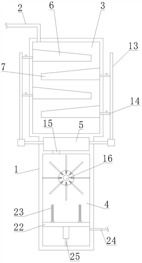
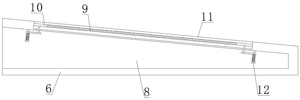
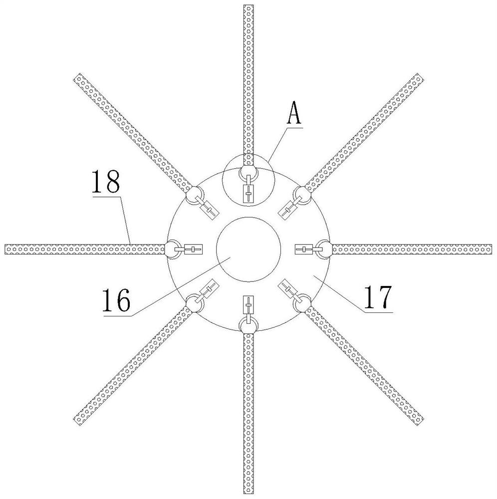
[0032] Such as Figure 1-4 As shown, a kind of environment-friendly water purification equipment for industrial production proposed by the present invention comprises equipment housing 1, industrial waste water conveying pipe 2, first chamber 3, second chamber 4 and water collection chamber 5, equipment housing The inside of the body 1 is provided with a first cavity 3, a second cavity 4 and a water collection cavity 5, the first cavity 3 is located above the second cavity 4, and the water collection cavity 5 is located between the first cavity 3 and the second cavity Between the cavities 4, the industrial wastewater delivery pipe 2 is installed on the top of the equipment housing 1 and communicated with the first cavity 3, the industrial wastewater delivery pipe 2 transports the industrial wastewater into the first cavity 3, and the industrial wastewater delivery pipe 2 is provided with a valve, through which the input of waste water is controlled. The first filter slope 6 an...
Embodiment 2
[0036] Such as Figure 5 As shown, this embodiment is basically the same as Embodiment 1. Preferably, the buffer protection mechanism 12 includes a connecting rod 1201, a first fixed rod 1202, a sliding seat 1203, a first spring 1204 and a limit block 1205; the connecting rod 1201 is connected by a bolt Fixedly installed on both sides of the bottom of the inclined plate 10, the first fixed rod 1202 is fixed and installed in the drainage chamber 8 by bolts, and the bottom end of the first fixed rod 1202 is connected with the limit block 1205, and the limit block 1205 acts as a limit It helps to prevent the sliding seat 1203 from being separated from the first fixed rod 1202; the sliding seat 1203 is installed on the connecting rod 1201 by bolts and is slidably connected with the first fixed rod 1202, and the sliding seat 1203 can be carried out along the first fixed rod 1202. Sliding, the first spring 1204 is sleeved on the first fixed rod 1202 and connected with the sliding se...
Embodiment 3
[0038] Such as Figure 6 As shown, this embodiment is basically the same as Embodiment 1. Preferably, the locking mechanism 19 includes a first limit cylinder 1901, a locking rod 1902, a first movable block 1903, a second spring 1904, a guide rod 1905 and a pull block 1906; the first limit cylinder 1901 is fixed on the installation roller 17 by bolts and is located in front of the limit card slot 21, the locking rod 1902 is vertically set and inserted into the first limit cylinder 1901, the locking rod 1902 is not Then cover the front opening of the limit card slot 21, the first movable block 1903 is slidably arranged in the first limit cylinder 1901 and connected with the locking rod 1902, the first movable block 1903 slides in the first limit cylinder 1901, The first limiting cylinder 1901 plays a limiting role on the first movable block 1903, the second spring 1904 is vertically arranged in the first limiting cylinder 1901 and connected with the first movable block 1903, an...
PUM
 Abstract
Description
Claims
Application Information
 - R&D Engineer
- R&D Manager
- IP Professional
- Industry Leading Data Capabilities
- Powerful AI technology
- Patent DNA Extraction
Browse by: Latest US Patents, China's latest patents, Technical Efficacy Thesaurus, Application Domain, Technology Topic, Popular Technical Reports.
© 2024 PatSnap. All rights reserved.Legal|Privacy policy|Modern Slavery Act Transparency Statement|Sitemap|About US| Contact US: help@patsnap.com


