
Compact power divider chip based on folded coil

A power divider and coil technology, applied in the field of compact power divider chips, can solve problems such as excessive chip area, achieve excellent performance and reduce size

Active Publication Date: 2021-08-06
SOUTHWEST CHINA RES INST OF ELECTRONICS EQUIP
View PDF10 Cites 2 Cited by
  • Summary
  • Abstract
  • Description
  • Claims
  • Application Information

AI Technical Summary

Problems solved by technology

[0007] The present invention aims to provide a compact power divider chip based on folded coils to solve the problem of excessive chip area

Method used


Image

  • Compact power divider chip based on folded coil
  • Compact power divider chip based on folded coil
  • Compact power divider chip based on folded coil

Examples


Embodiment

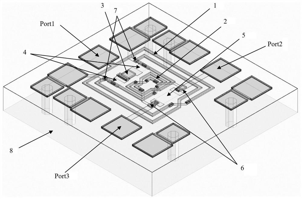
[0034] like figure 1 As shown, this embodiment proposes a compact power divider chip based on a folded coil, including:

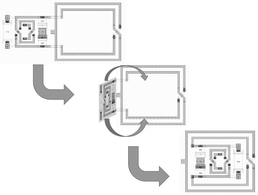
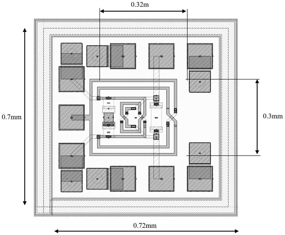
[0035] A folded coil, the folded coil includes a first-stage coupling coil and a second-stage coupling coil that are connected; the first-stage coupling coil is formed by two completely symmetrical upper and lower inductances intertwined with each other, and the first-stage coupling coil The coil tap is connected to the combining port of the power divider chip, and the signal reaches the coil tap of the first-stage coupling coil from the combining port and is divided into two channels to transmit clockwise and counterclockwise respectively; It is formed by two completely symmetrical upper and lower inductors intertwined with each other. After the first-stage coupling coil reaches the second-stage coupling coil, the signal is also transmitted to the two power division ports of the power divider chip clockwise and counterclockwise respectively; and, the seco...


PUM


Abstract

The invention provides a compact power divider chip based on a folded coil. The compact power divider chip comprises the folded coil, an RC series network and two resonant capacitors, wherein the folded coil comprises a first-stage coupling coil and a second-stage coupling coil which are connected; the first-stage coupling coil is formed by mutually winding two inductors which are completely symmetrical up and down, and a coil tap of the first-stage coupling coil is connected with a combining port of the power divider chip; the second-stage coupling coil is formed by mutually winding two inductors which are completely symmetrical up and down; the second-stage coupling coil is folded into the first-stage coupling coil; the RC series network is arranged in the first-stage coupling coil and comprises a first-stage RC series network and a second-stage RC series network; the first-stage RC series network is connected with two power division paths of the first-stage coupling coil; the second-stage RC series network is connected with two power division paths of the second-stage coupling coil; and the two resonant capacitors are connected to the joint of the first-stage coupling coil and the second-stage coupling coil and are connected to the ground. According to the compact power divider chip, the size of the power divider chip can be greatly reduced, and excellent performance is shown.

Description

technical field [0001] The invention relates to the field of microwave radio frequency integrated circuits, in particular to a compact power divider chip based on a folded coil. Background technique [0002] The operating bandwidth is an important indicator of the power divider, which is defined as the operating frequency range where the indicators of interest all meet the operating conditions. The bandwidth of the power divider is usually measured by the relative bandwidth coefficient B, which is defined as: [0003] [0004] where f h High-end cutoff frequency for power divider operation, f l Low-end cutoff frequency for power divider operation. [0005] The chip area is directly related to the cost of the chip and the integration of the upper-layer system, and is an important concern of the chip. [0006] In the existing one-to-two power divider products, for the power divider with k<1.5, in order to reduce the layout area, the lumped parameter design is usually...

Claims


Application Information

Patent Timeline
Patent Type & Authority Applications(China)
IPC IPC(8): H01L25/16H01L27/06H01P5/16
CPCH01L25/16H01L27/0682H01P5/16
Inventor 韩思扬刘云刚蔡雪芳王海龙
Owner SOUTHWEST CHINA RES INST OF ELECTRONICS EQUIP
Learn More